

What Makes Nemesis II a Premium Concrete-Drilling Range?
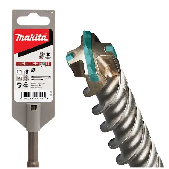
Makita Nemesis II brings four-cutter geometry, centering features and efficient dust removal to professional concrete drilling. Its appeal is practical: accurate anchor holes, stable starts and a cutting head designed to keep working when concrete contains hard aggregate or reinforcement.
The useful engineering detail is how the carbide changes across the range. A cross-shaped head can be a one-piece insert supported by steel, a three-piece insert assembly, or a solid carbide working head. Understanding the carbide layout and steel support helps match these constructions to the appropriate SDS-Plus and SDS-Max references.
Our starting point is the job: substrate and reinforcement, rotary-hammer capacity, hole diameter and depth, then the failure mode the head and body must withstand. For the commercial background, our Makita SDS-Plus pricing analysis covers the purchasing decision separately.
Nemesis II Head Construction by Diameter
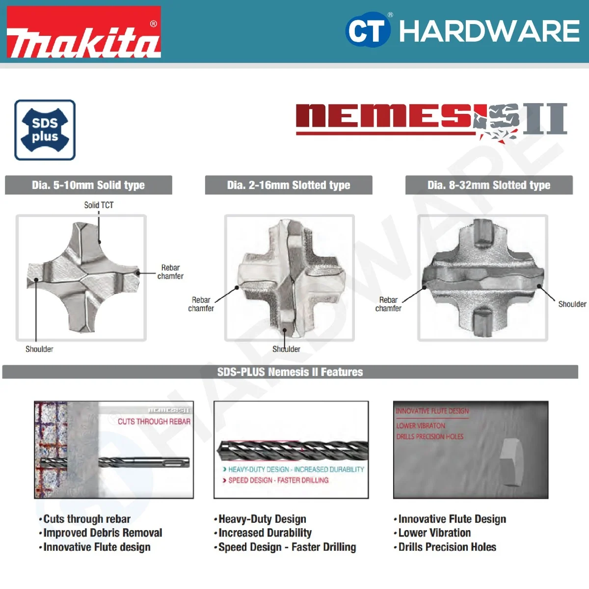
The UK Nemesis II page and the New Zealand SDS-Plus listing support the following three-way map. The dimensions belong to those references and the original panels.
| Construction in the illustrations | What the carbide layout means | SDS-Plus range shown |
|---|---|---|
| Monobloc cross insert | One carbide cross seated in a steel-supported head | 12–16 mm |
| Three-piece cross head | One main carbide insert and two side inserts; four cutting edges | 18–32 mm |
| Solid carbide head | One carbide head forming the four-cutter working end | 5–10 mm |
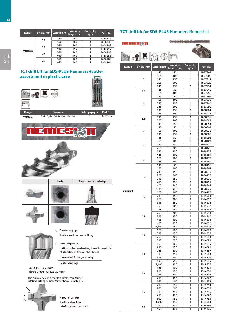
Keep the catalogue edition with the specification. Makita India’s 2025 accessories catalogue, page 44, labels Solid TCT (5–20 mm) and three-piece TCT (22–32 mm). The head illustrations remain useful for identifying construction, while that regional catalogue illustrates why a diameter alone cannot identify every Nemesis II head sold worldwide. Confirm the market, part number and delivered construction when comparing samples.
View the original catalogue page: dimensions and carbide construction
The Monobloc Cross Insert
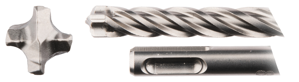
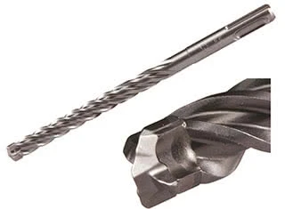
A monobloc cross insert integrates the four-cutter shape into one carbide component, with steel support around and below it. Makita’s panel calls this a one-piece cutter at 12–16 mm; the UK page describes this band as slotted TCT.
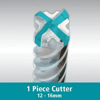
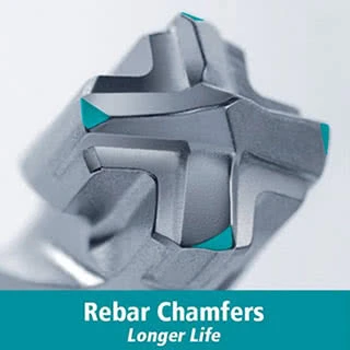
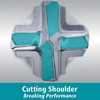
The distinction is the physical carbide-and-steel arrangement. One cross-shaped insert can form four cutting edges while the head still contains supporting steel around that insert. In broader manufacturer terminology, monobloc can also describe a one-piece full head, so a purchasing drawing should show the carbide outline, steel support and joint.
The other two panels show features within the working geometry. Rebar chamfers modify the local contact edge; cutting shoulders contribute to the concrete-breaking profile. Their performance depends on dimensions, edge preparation, carbide and support. The teal areas are explanatory highlights in the illustrations.
The Three-Piece Cross Head
A three-piece cross head uses a main carbide insert and two side inserts. Together they form four cutting edges. Three pieces therefore describes the assembly; it does not turn this into a three-cutter or Y-head bit.
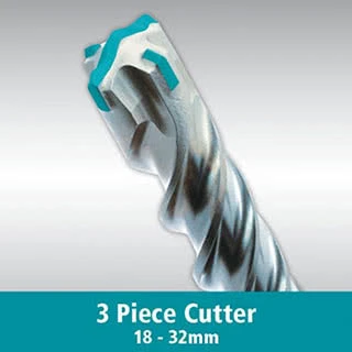
The main insert spans the drilling face and the side inserts complete the cross arrangement. Larger diameters allow a different balance between carbide volume, supporting steel and open passages into the flutes. During manufacture, insert position, joint integrity, finished gauge and runout must work together.
The illustrated SDS-Plus band is 18–32 mm. For a sample order, identify the actual head on the target reference, particularly where a another regional catalogue gives a different transition diameter. Our multi-insert versus monobloc guide explains the construction checks.
The Solid Carbide Head
A solid carbide head forms the complete four-cutter working head as one carbide component. In the original panel it is labelled 5–10 mm. This full-head construction differs from a cross insert seated within a steel-supported head.
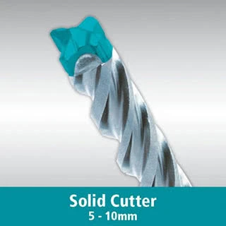
A solid head integrates the cutting geometry and the carbide between the cutting edges. It still needs a controlled connection to the steel body. Edge count, carbide construction and the head-to-body joining route are three separate specifications.
When we evaluate this architecture for an OEM project, we check the substrate and hammer first, then head dimensions, carbide toughness, joint quality, gauge retention and sample-drilling results. A photograph establishes the visible layout; the approved manufacturing specification establishes the alloy and joining process. See our full-carbide-head joining guide.
SDS-Plus and SDS-Max Need Separate Specifications
SDS-Plus and SDS-Max identify different machine interfaces. Both can carry four-cutter heads, and the same brand-family name can cover different carbide constructions. Select a rotary hammer whose rated capacity fits the hole diameter and depth.
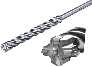
Makita New Zealand’s SDS-Max Nemesis II listing gives a separate map: 12–32 mm full carbide and 35–52 mm slotted TCT. The illustration of a slotted SDS-Max head is useful for recognizing that construction; it should not be used to assign every current SDS-Max reference to a three-piece layout.
For quotations, record part number, interface, diameter, working length and overall length separately. One current New Zealand SDS-Plus example is E-20971, shown as 6 × 165 mm with 100 mm working length. Preserve the SKU when comparing regional length descriptions.
Rebar, Dust Removal and Performance Claims
Hard aggregate challenges carbide wear resistance; reinforcement creates a different contact condition with higher local torque and edge loading. Start the comparison with those conditions, then assess the head, its support and the dust-removal path. Planned drilling through structural reinforcement follows the approved project drilling plan.
Roundness, finished diameter and entry-edge condition are useful acceptance checks. The comparison below shows two-cutter and four-cutter head layouts alongside their hole profiles.
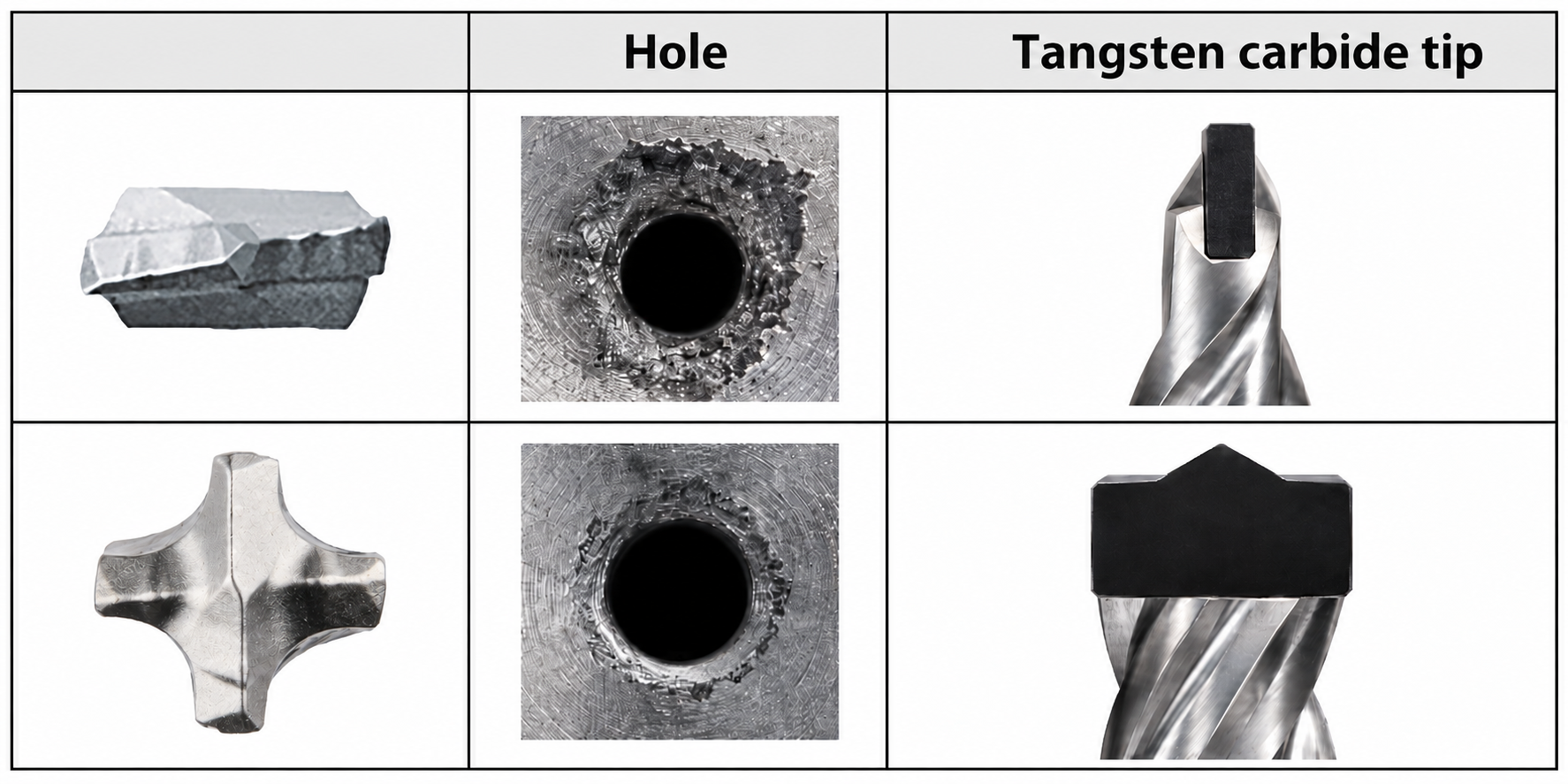
Centering geometry helps place the hole. Flutes move broken material away from the cutting face, and the wear mark supports the assessment of hole-diameter suitability for anchoring. Follow the selected anchor’s drilling and cleaning instructions throughout the bit’s usable life.
Makita New Zealand states 20% faster drilling and 50% longer life against its previous SDS-Plus range; the UK page describes up to 50% more holes against standard rotary-hammer bits. Keep each statement with its published comparator. These percentages serve the named Makita comparison and should not be transferred to a different head, diameter or OEM sample.
For a useful trial, compare the same hammer, diameter, depth, concrete and reinforcement conditions. Record usable hole count, drilling time, final hole gauge and the wear or damage that ends the test.
Building a Zhonghuan OEM Range against This Benchmark
We manufacture SDS-Plus and SDS-Max drill bits for distributors and private-label tool brands. This benchmark becomes a concrete specification: application, machine, required sizes, carbide construction, joining, body treatment and sample acceptance.
- Cross-head programme: our SDS-Plus 5X range covers Ø5–25 mm with brazed four-cutter geometry and four-flute debris removal. We confirm the insert layout on the approved sample drawing.
- Full-carbide-head programme: our SDS-Plus full-head range covers Ø4–25 mm. Our ZHMAX-8 SDS-Max range also currently covers Ø4–25 mm and uses our resistance-friction-welded head-to-steel connection.
- Larger multi-insert SDS-Max: ZHMAX-7 covers Ø16–45 mm, using a full-width main carbide blade and two inclined, axially set-back side inserts. It is a separate application-led construction.
Planning an OEM Nemesis II benchmark? Send the target reference or head photo, hole diameter and length, rotary-hammer model, material and approximate quantity. We will propose the suitable construction and sampling specification, with private-label packaging options. Explore our SDS-Plus and SDS-Max ranges.
Frequently Asked Questions
Are all Makita Nemesis II bits solid carbide head designs?
The family contains different constructions. The UK/New Zealand SDS-Plus references distinguish a solid head, a one-piece cross insert and a three-piece head by diameter. Other catalogues show different transition diameters, so confirm the exact part and market.
How can three carbide pieces form a four-cutter head?
The main insert forms two cutting edges and the two side inserts add the other two. Carbide piece count and cutting-edge count describe different aspects of the same head.
What does monobloc cross mean here?
Here it identifies the pictured one-piece cross insert supported by steel. The broader word monobloc means one carbide component and can also overlap with full-head terminology; the drawing should identify the complete construction.
Why do some Nemesis II catalogues show different diameter ranges?
The UK/New Zealand pages and illustrated panels show 5–10 mm solid, 12–16 mm one-piece and 18–32 mm three-piece SDS-Plus heads. Makita India’s 2025 catalogue labels Solid TCT at 5–20 mm and three-piece TCT at 22–32 mm. Use the relevant catalogue and actual SKU.
Does the SDS-Plus head map also apply to SDS-Max?
SDS-Max is a separate programme. Makita New Zealand lists full carbide at 12–32 mm and slotted TCT at 35–52 mm; match the supplied part number and machine rather than transferring the SDS-Plus map.
Official References
Official product pages and catalogue diagrams checked on 24 October 2026. Construction explanations combine these references with our engineering reading of the photographs. The diameter boundaries remain tied to the market and catalogue identified above.


