

Where Milwaukee M/2 Fits
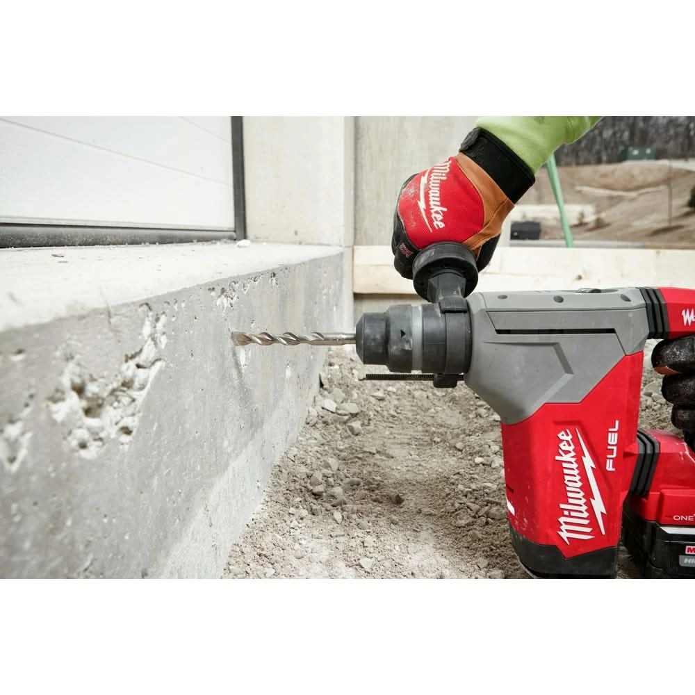
Milwaukee M/2 two-cutter SDS-Plus bits combine a shaped carbide tip, supported cutting edges and a variable flute for general concrete drilling. The supplied 48-20-7490 images make a useful engineering reference: they show the head, flute, application chart and five-size assortment rather than just a product silhouette.
Select the substrate and likely reinforcement contact first, then the SDS-Plus rotary hammer, hole diameter and depth. Brick and block anchor holes differ from hard-aggregate concrete and planned reinforcement crossings. Match the bit to the hammer’s rated drilling range and the anchor’s specified hole geometry.
Centering Tip and Breaker Points Do Different Jobs
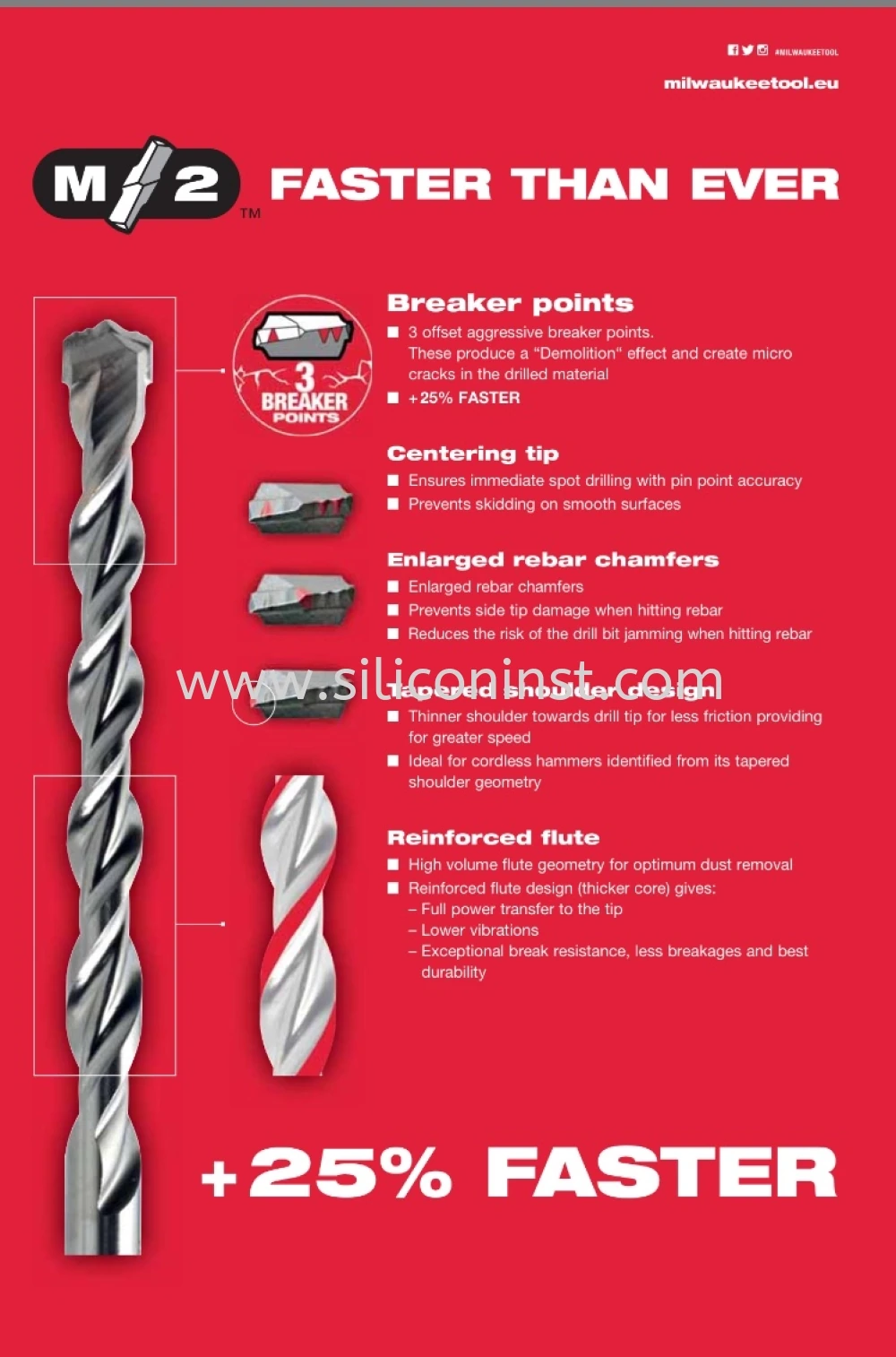
Milwaukee lists a centering tip separately from Breaker Points on its M/2 kit page. The central tip helps establish the drilling position. The breaker features shape the contact along the carbide cutting profile.
Our mechanical reading is that small, offset contact features concentrate the initial hammer load into local fracture zones. Rotation brings successive parts of the cutting profile into contact with fresh material. This gives the concrete several local breaking actions instead of treating the carbide as a plain, uninterrupted chisel edge.
The supplied European sheet and European M2 description identify three chip breakers. Three breaker points are not three radial cutting arms. M/2 remains a two-cutter geometry; the number of profile features, main cutting edges and separate carbide pieces are different specification fields.
Rebar Guards: Edge Protection and Application Choice
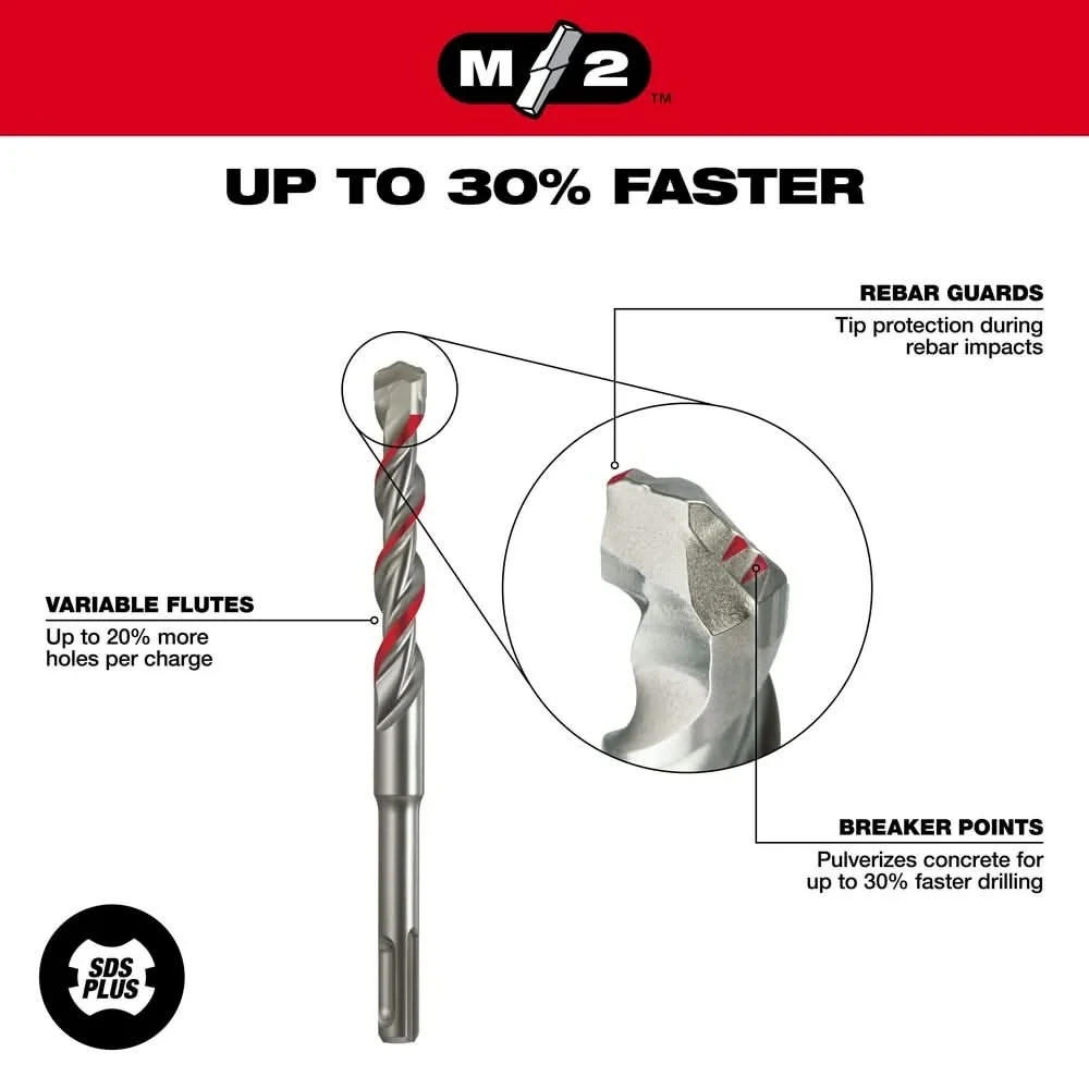
Rebar Guards refers to protective head geometry. The European material describes enlarged chamfers intended to reduce side-tip damage during reinforcement impacts. In mechanical terms, the vulnerable carbide corner and its local support matter when the head meets a hard inclusion unevenly.
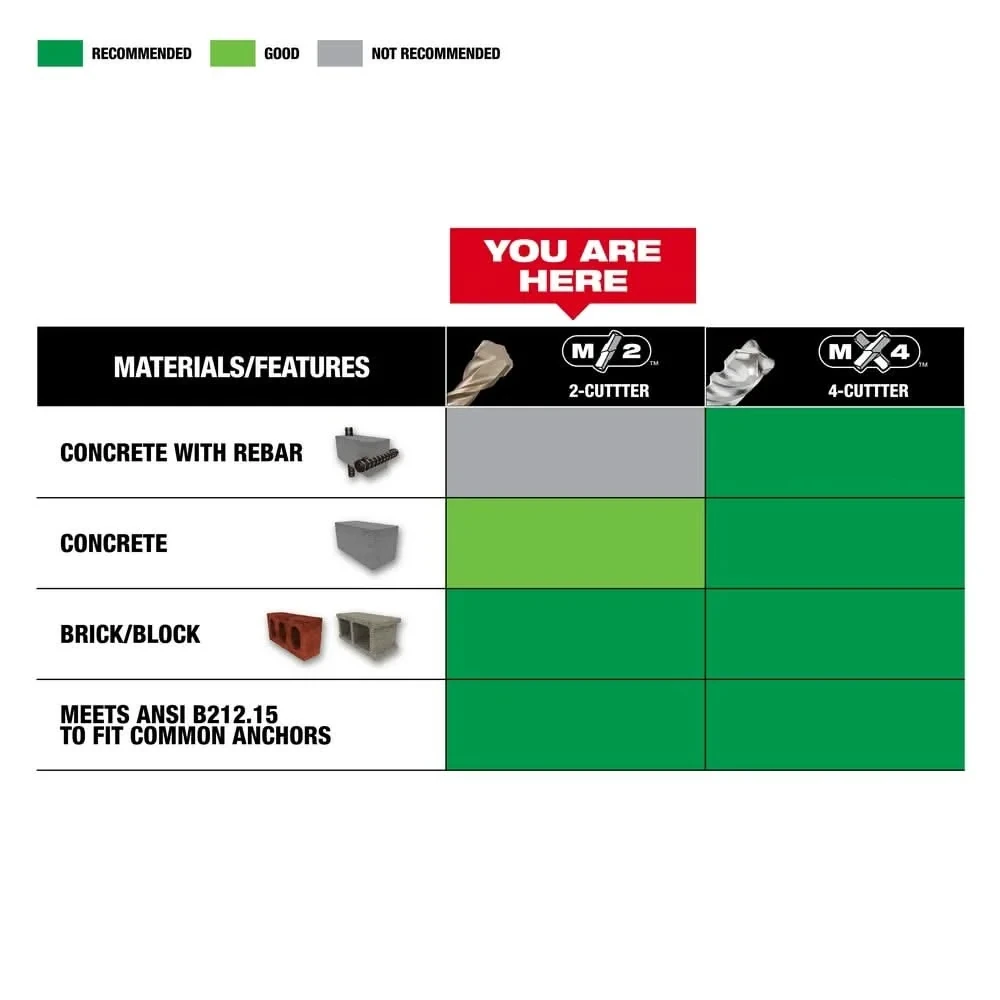
Read that protection alongside the supplied selection chart: M/2 is rated for brick/block and general concrete, while the chart recommends MX4 for concrete with rebar and marks M/2 as not recommended in that row. A feature that improves survival at a steel encounter is different from selecting a programme for repeated reinforcement crossings.
For planned reinforced-concrete drilling, compare the exact MX4 or other dedicated head configuration by SKU, diameter and hammer platform. Follow the project’s approved drilling position and reinforcement-cutting plan.
Variable Flute, Tapered Shoulder and Reinforced Core
The US M/2 description links its variable flute with debris evacuation and cordless productivity. European material also identifies a tapered shoulder and a thicker core. The red trace in the supplied graphic highlights the flute path.
These features address different losses: the shoulder controls clearance behind the head, the flute provides transport space, and the core carries impact and torque. Packed cuttings make the head rework crushed material and increase resistance. The design task is to balance a supported core with sufficient debris volume, especially as working length increases.
Impact energy travels from the hammer through the shank, steel body and joint into the carbide. A reinforced flute does not by itself specify body steel, heat treatment or joining parameters; those belong on the manufacturing drawing. Flute transport also complements dust extraction and the anchor’s required hole-cleaning procedure.
Wear Marks and Anchor-Hole Diameter
Milwaukee describes Wear Mark Indicators as a guide to the point at which the bit no longer meets the relevant ANSI diameter requirement. The supplied chart names ANSI B212.15 in connection with common anchor-hole sizing.
This is a gauge-retention issue: a carbide edge can still break concrete after peripheral wear has changed the effective hole diameter. For procurement acceptance, record the nominal diameter, the agreed measurement method and wear limit together. Use the specific anchor instructions for hole diameter, embedment and cleaning.
Use the wear mark as an inspection trigger, then confirm the diameter with the agreed gauge before continuing anchor-hole work.
Read the 30%, 25% and 20% Claims in Context
The supplied US graphics show a speed improvement of up to 30% and up to 20% more holes per battery charge. Milwaukee’s 2019 US accessory catalogue uses those M/2 figures; the current US product description continues to emphasize the holes-per-charge figure.
The European graphic shows a 25% speed improvement. The 2024 UK catalogue labels its 25% comparison against the previous generation. These are separate manufacturer references, not percentages to add together or results measured by Zhonghuan.
For a sample comparison, hold diameter, working length, hammer, battery, concrete and hole depth constant. Measure time per completed hole and completed holes per charge separately; a speed claim does not automatically equal the same percentage reduction in energy per hole.
48-20-7490 Kit vs 48-20-7410 and 48-20-7411
The current 48-20-7490 listing and the supplied kit graphic show the following five bits. These are diameter × overall-length labels, with one of each size.
The separate 48-20-7411 is 3/16 in diameter, 4 in usable length and 6 in overall length. Its 4 in middle dimension is not the 4 in overall length of the shorter 48-20-7410.
Keep the kit code separate from individual-bit codes: 48-20-7490 identifies an assortment, not one diameter and length. The matrix here follows the current US listing and 2021 catalogue. Confirm that matrix against the supplied pack when ordering.
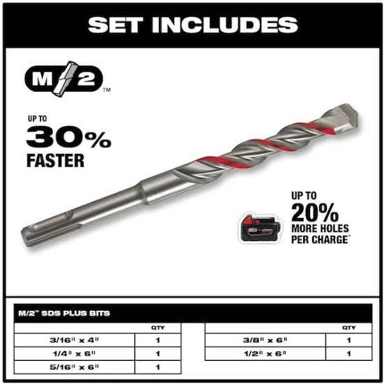
| Diameter | Metric diameter | Listed overall length | Quantity |
|---|---|---|---|
| 3/16 in | 4.7625 mm | 4 in · 101.6 mm | 1 |
| 1/4 in | 6.35 mm | 6 in · 152.4 mm | 1 |
| 5/16 in | 7.9375 mm | 6 in · 152.4 mm | 1 |
| 3/8 in | 9.525 mm | 6 in · 152.4 mm | 1 |
| 1/2 in | 12.7 mm | 6 in · 152.4 mm | 1 |
| Individual part | Diameter | Usable length | Overall length |
|---|---|---|---|
| 48-20-7410 | 3/16 in · 4.7625 mm | 2 in · 50.8 mm | 4 in · 101.6 mm |
| 48-20-7411 | 3/16 in · 4.7625 mm | 4 in · 101.6 mm | 6 in · 152.4 mm |
German-Made References and Older 44 Magnum Listings
The supplied head graphic says German Made, and European M2 catalogues identify the family as made in Germany. Keep origin tied to the selected regional article and supplied lot. The brand name alone does not specify a factory, OEM relationship or carbide grade.
Some marketplace listings retain the older 44 Magnum name, different finish fields and package dimensions. Those entries are useful historical locators, but the current manufacturer page identifies 48-20-7411 as M/2. Use that exact part number and its current specifications for comparison; confirm finish and origin on the marked sample when purchasing.
Build an OEM Benchmark from the Construction
At Zhonghuan, we translate the reference into a specification for our own SDS-Plus programme: substrate, expected reinforcement contact, hammer model, diameter and working length come before head, carbide, steel and joining choices.
For a premium two-cutter sample, inspect centering symmetry, breaker profile, chamfer support, carbide seating, joint coverage, finished runout and gauge. Test starting position, drilling time, wear, edge damage and head retention under the agreed conditions. A reinforced-concrete upgrade is a separate configuration and sample plan.
| Proposed route | Configuration for confirmation | Sample acceptance |
|---|---|---|
| A — Premium 2-cutter | Self-centering carbide insert, supported edges, brazed joint and application-matched flute/core | Starting position, rate, gauge, edge wear and tip retention |
| B — Reinforced-concrete upgrade | Our four-cutter full-carbide head joined to steel by resistance friction welding; dimensions matched to the hammer | Reinforcement engagement, joint integrity and gauge retention |
Send us target material, diameter × working length and expected quantity, with a hammer model or reference if available. We confirm the construction, samples and private-label packaging through an OEM quotation. Explore our SDS-Plus range and the separate Diablo two-cutter analysis.
Official References and Image Notes
The six images are supplied Milwaukee reference material, including US kit graphics and a European feature sheet. We retain their market-specific comparisons and explain the mechanics as our engineering interpretation. We use application, geometry and dimension fields as OEM benchmarks, with acceptance confirmed on our samples.
- Milwaukee 48-20-7490 — current kit contents and M/2 features
- Milwaukee 48-20-7410 — 3/16 × 2 × 4 in
- Milwaukee 48-20-7411 — 3/16 × 4 × 6 in
- Milwaukee Europe — M2 two-cutter geometry
- Milwaukee 2019 US catalogue — historical claims and kit listing
- Milwaukee 2021 US catalogue — kit size matrix
- Milwaukee 2024 UK catalogue — M2 features, origin and comparison basis
Frequently Asked Questions
Do three breaker points make M/2 a three-cutter?
No. The three chip-breaking features sit on a two-cutter profile. Feature count, main cutting-edge count and carbide-component count are different fields.
Do Rebar Guards make M/2 equivalent to MX4?
No. They protect the head at difficult contact. The supplied application chart selects MX4 for concrete with rebar and marks M/2 as not recommended for that application.
Is the centering tip the same feature as a breaker point?
They have different jobs. The centering tip establishes the start; breaker points shape local fracture along the cutting profile.
What does the wear indicator tell the buyer?
Milwaukee describes it as an aid for identifying wear beyond the relevant ANSI diameter requirement. Verify gauge and anchor requirements; the mark is not an anchor pull-out result.
Are the 4 in dimensions of 48-20-7410 and 48-20-7411 the same?
No. 48-20-7410 has 4 in overall length and 2 in usable length. 48-20-7411 has 4 in usable length and 6 in overall length. Both are 3/16 in diameter.
Why do the images show 30% and 25% faster?
They are different regional manufacturer references. The UK catalogue identifies its 25% comparison against the previous generation. Keep the comparison basis and generation attached to each figure.
Is M/2 made in Germany?
The supplied head graphic and European M2 catalogues identify German manufacture. Confirm the selected regional SKU and lot from its packaging and product markings.
What should an OEM buyer send?
Material, diameter × working length and quantity. A hammer model and benchmark help us confirm the head, materials, joining, sample criteria and private-label packaging.


