

Read the segment as a complete cutting system
These buyer-facing illustrations separate visible profile, working-face texture, waterway and the brazed crown assembly. They are geometry references rather than factory inspection photographs.
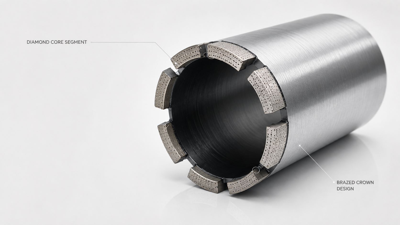
Segment position on the barrel
Use the installed crown view to confirm spacing, orientation and the segment-to-barrel joint before discussing top profile.
- Installed crown
- Segment spacing
- Brazed joint location
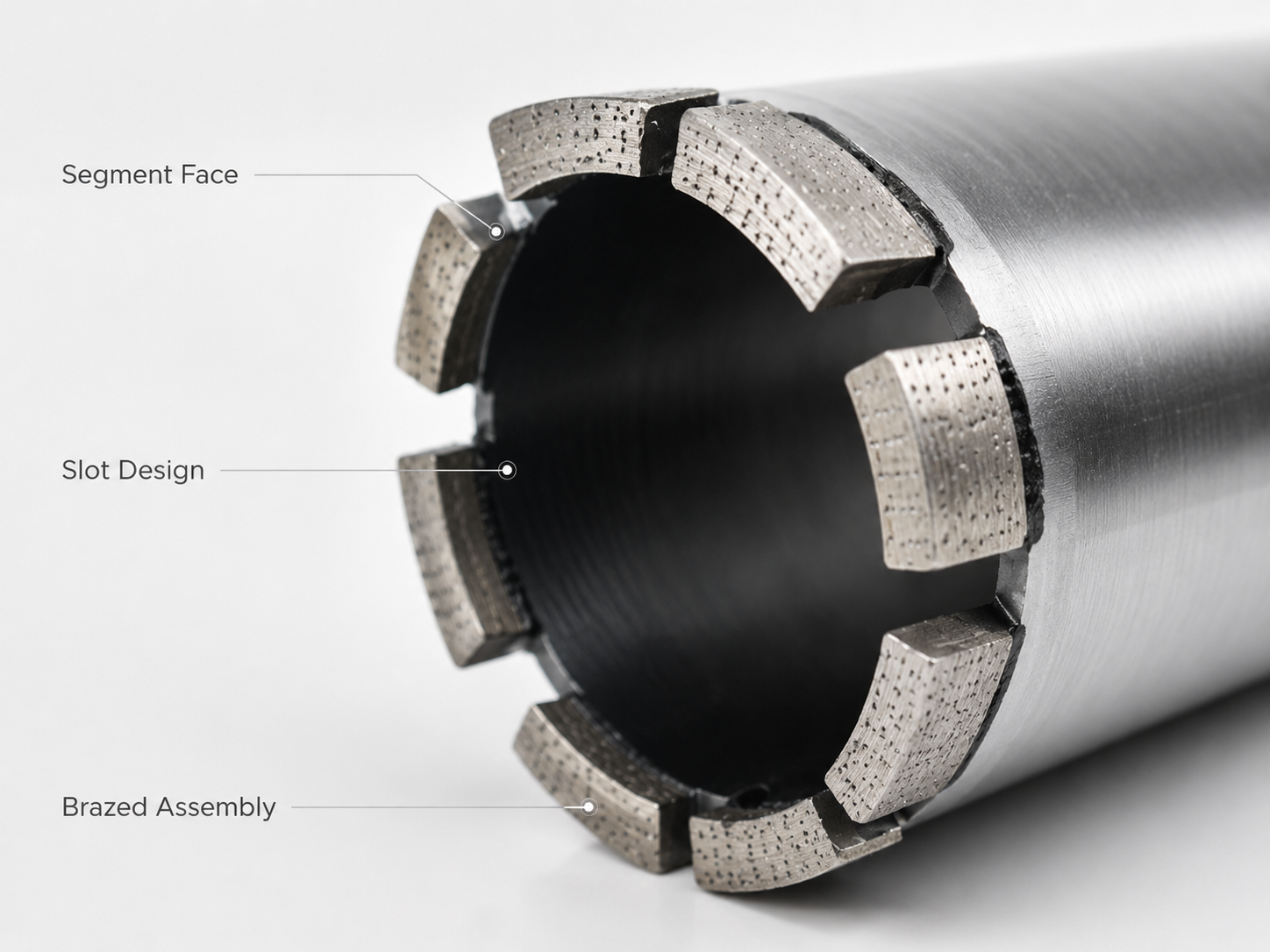
Working face, slot and joint
The cutting face, flow path and attachment point perform different jobs and should be written as separate RFQ fields.
- Working face
- Waterway slot
- Brazed assembly
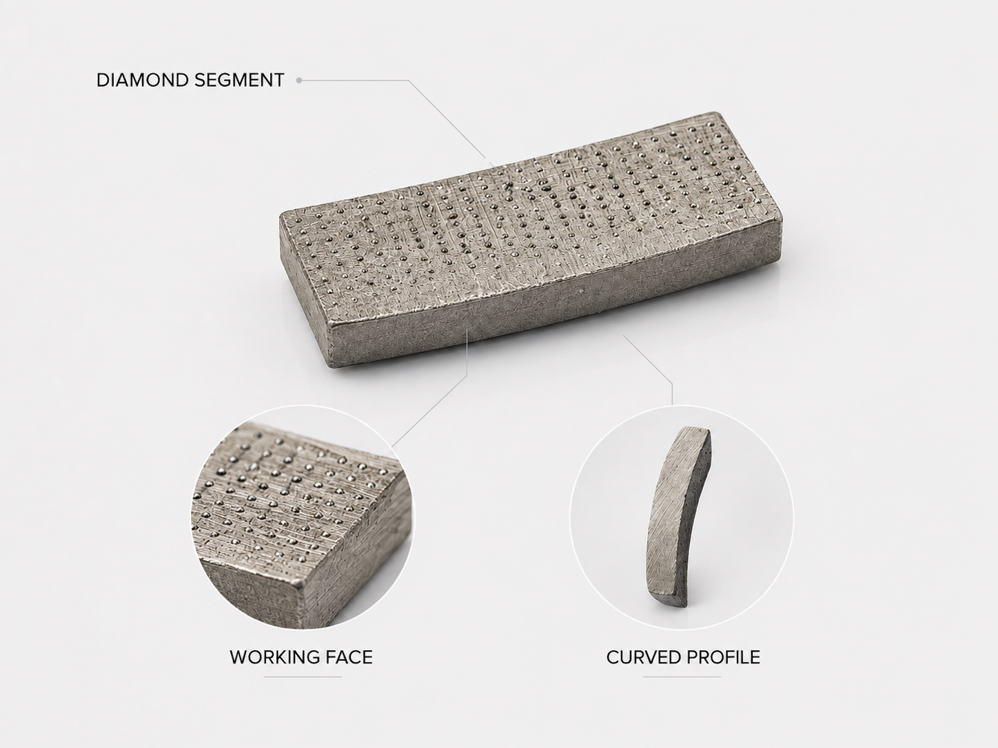
Curved profile and working-face texture
A loose segment view makes profile radius, usable matrix and face texture easier to approve before production.
- Curved profile
- Working-face texture
- Approval reference
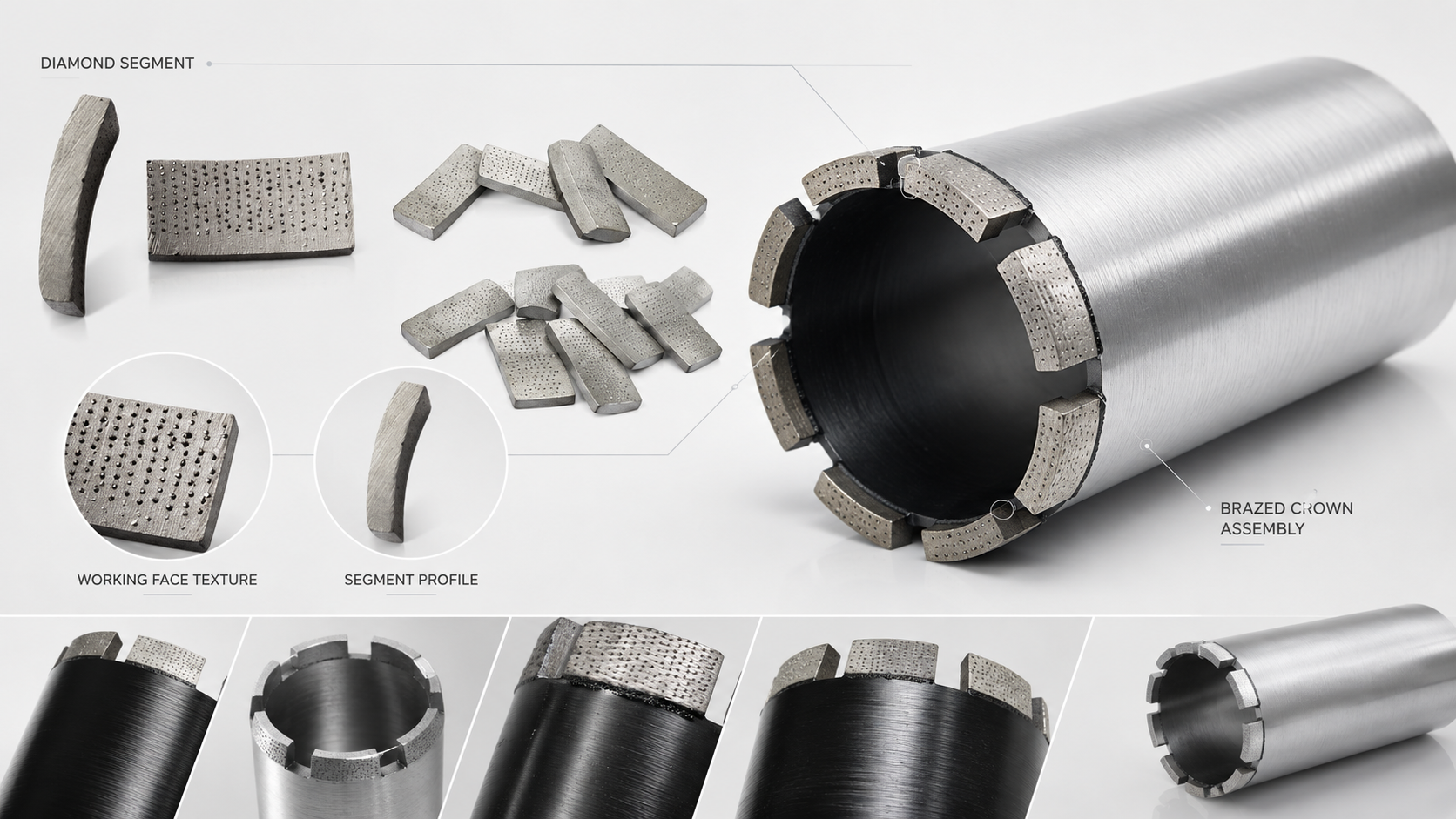
Loose segments to finished crown
Use one visual set to align the loose segment, installed orientation and finished barrel during sample approval.
- Loose segments
- Installed orientation
- Finished crown
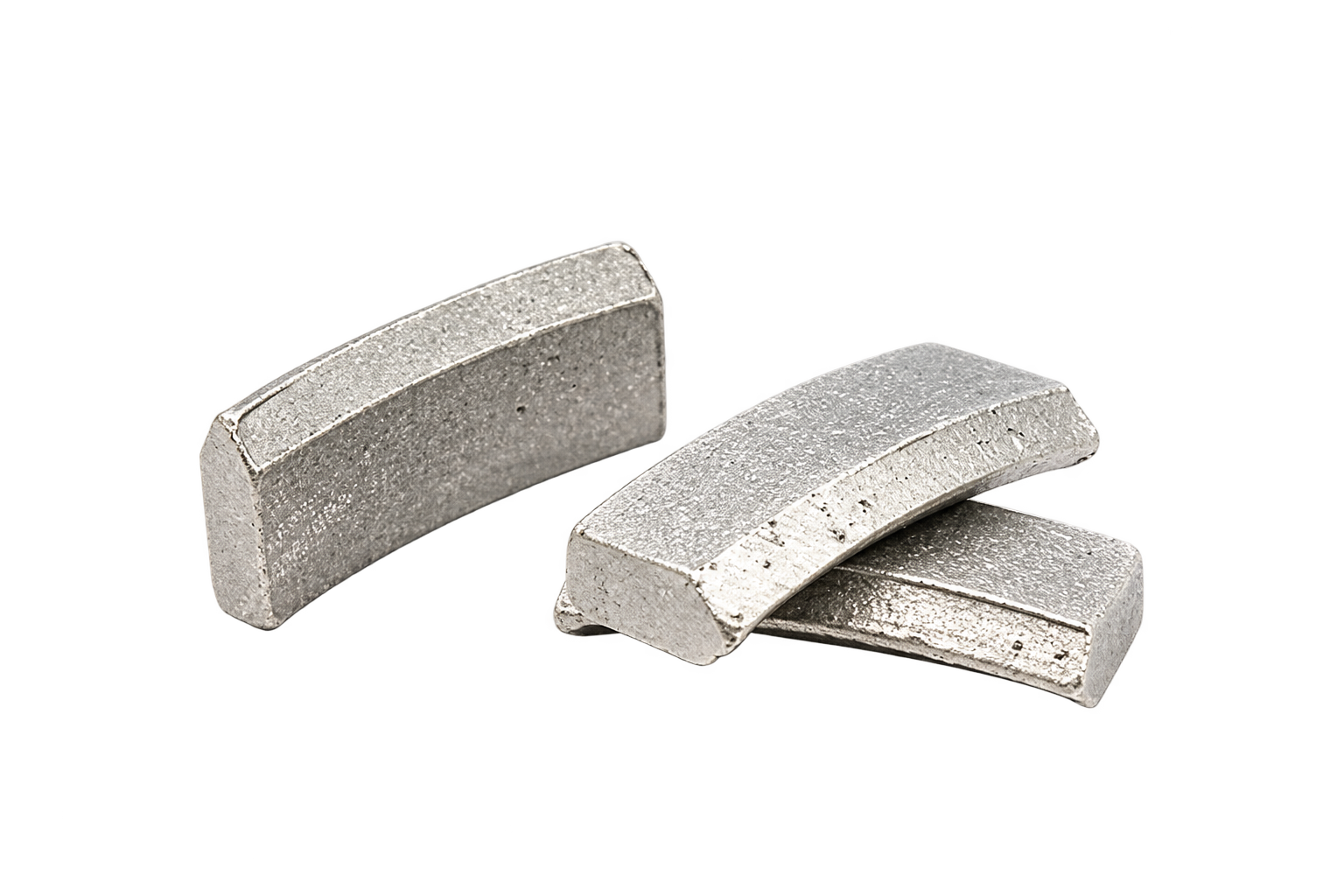
Roof-top segment reference
The raised ridge concentrates first contact and then wears toward a flatter working face. Approve ridge height and side profile from a drawing.
- Raised centre ridge
- Controlled first contact
- Side-profile approval
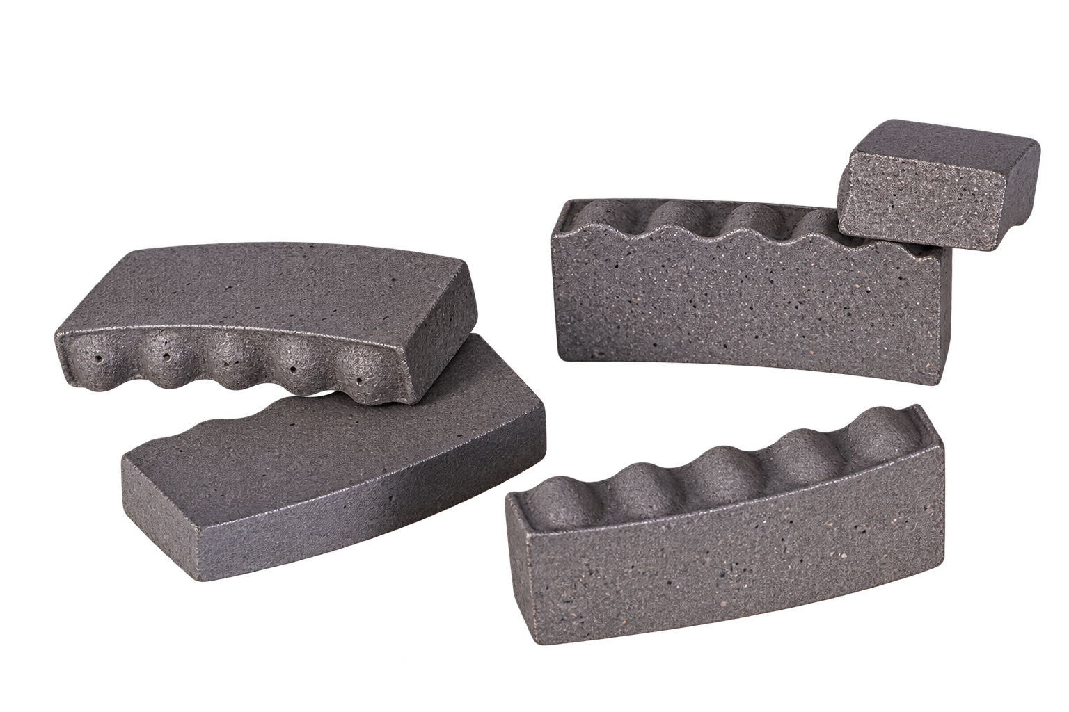
Dimpled working-face variants
Use the visible dots as a surface-feature reference only. They do not by themselves prove full-depth ordered diamond placement.
- Surface feature
- Face-opening reference
- Not placement proof
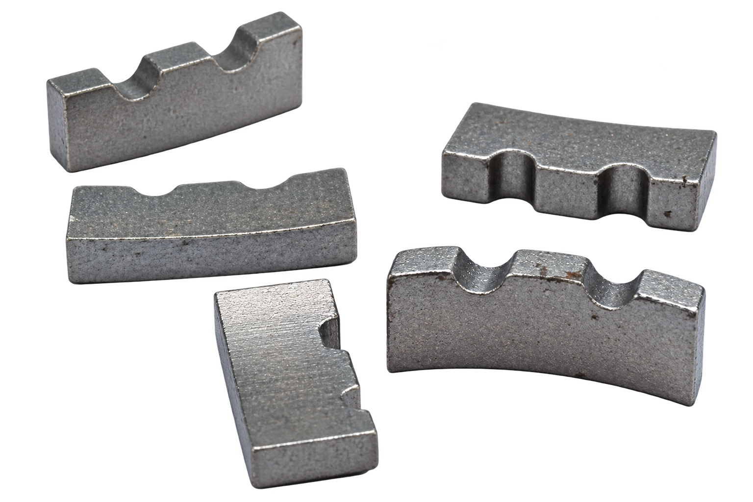
Castellated segment variants
Repeated peaks and valleys alter the initial contact pattern. Tooth count, radius and depth must be fixed on the signed drawing.
- Castellated profile
- Repeated contact zones
- Drawing-controlled geometry
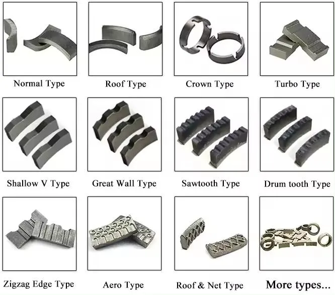
Supplier profile naming reference
This catalogue chart records common market names. Treat it as terminology evidence, not as a normalized standard or Zhonghuan production photograph.
- Catalogue vocabulary
- Multiple profile names
- Reference only
Quick Answer: Specify Four Separate Layers
A professional diamond core bit specification should not treat every visible feature as a segment shape. We separate four layers: top profile, diamond arrangement inside the matrix, waterway design, and segment-to-barrel attachment. Keeping these fields separate lets a distributor compare samples without accepting a catalogue label that hides the actual construction.
The supplied profile reference shows four buyer-facing starting families: standard flat, turbo-grooved, crown/notched, and roof or tapered-wedge. They influence first contact, centering and face clearance. Bond, grit, concentration, segment width, machine power and cooling still determine whether the bit cuts productively.
Four Buyer-Facing Profile Families
Standard flat
A flat working face spreads load across the segment width and gives a predictable general-purpose starting point for wet coring. It is simple to inspect and easy to hold against a reference sample. It does not create a self-centering ridge, so machine alignment and start control remain important.
Turbo-grooved
Shallow grooves or ribs reduce the initial contact area and create local paths across the face. This can improve entry and face clearance, especially when the bond exposes diamond correctly. Turbo is not a substitute for a softer or harder bond selected for the actual aggregate.
Crown or notched
A crown profile breaks the top face into repeated contact zones. The geometry can make initial engagement more positive and create additional edges as the profile wears in. The RFQ should show the notch count, depth and reference photograph because suppliers use the word crown for several different mould geometries.
Roof or tapered wedge
A raised ridge or tapered face concentrates first contact near the centre of the segment. This is useful when controlled entry and rapid opening of the cutting face matter. The profile normally wears toward a flatter face, so performance after run-in still depends on the matrix and diamond layout.
Dotted Top, Great Wall and Market Profile Names
Dotted or dimpled top describes recesses or raised contact features on the visible working face. The feature can change initial contact area, coolant retention and face opening, but it does not prove that diamonds are positioned in an ordered three-dimensional array through the full segment depth.
Great Wall is a market name for a castellated or crenellated profile with repeated high and low contact zones. The exact tooth count, notch radius and depth are not standardized, so the signed drawing and side-profile photograph remain the real specification.
Supplier catalogues also use names such as normal, shallow-V, sawtooth, drum-tooth, aero and roof-and-net. These labels are useful for discussing a visual reference, but they are not a shared international geometry standard. Translate every catalogue name into a drawing, dimensions and an approved sample before production.
Profile Is Not Diamond Layout
Random, uniform and ARIX-style ordered diamond placement describe the distribution of crystals through the metal-bond matrix. They do not define whether the visible top is flat, turbo, crown or roof. An ordered-array segment can use any approved top profile that the mould and application require.
For a detailed comparison of diamond placement, use our ordered diamond array vs uniform distribution guide. In an OEM RFQ, write the top profile and the internal diamond layout on separate lines.
Waterways, Slots and Dimples
Inter-segment gaps, tube slots and surface dimples manage coolant arrival and slurry evacuation. A gap is the space between adjacent segments. A tube or crown slot creates a deeper flow path. A dimple is a local recess in the working face. Their value depends on diameter, depth, water supply and slurry volume; they are not universal upgrades.
Large or deep wet-coring programs may need more open flow paths, while smaller diameters can lose useful segment area if the crown is over-slotted. Confirm water flow and barrel geometry with the machine program instead of selecting a slot from appearance alone.
Attachment Is a Separate Decision
After a segment is hot-pressed and sintered, it still needs to be joined to the steel barrel. Laser welding, high-frequency induction brazing and silver brazing describe the joint route, not the segment profile. See our diamond core bit attachment methods guide for the correct two-axis specification.
Application Selection Matrix
| Job priority | Profile starting direction | Confirm with it |
|---|---|---|
| Balanced wet coring | Flat or modest crown | Bond, segment width, water flow |
| Controlled entry | Roof or tapered wedge | Rig alignment, run-in behaviour |
| Face clearance priority | Turbo-grooved or notched crown | Bond exposure, slurry removal |
| Consistent diamond exposure | Approved profile + ordered layout | Layer spacing, grit, concentration |
| Deep or large-diameter wet coring | Application-matched profile | Gaps, slots, water volume, barrel wall |
OEM RFQ Wording
Diamond core bit Ø132 mm × 450 mm for wet reinforced-concrete coring. Segment top profile: approved crown/notched reference, drawing and photograph attached. Segment dimensions: length × width × total height stated on drawing. Diamond layout, grit, concentration and bond direction matched to the approved substrate and rig. Waterway: inter-segment gap and tube-slot dimensions stated separately. Segment-to-barrel joint: approved laser-welded or brazed route with sample acceptance. Production lot must match the signed reference sample.
This wording prevents a supplier from substituting diamond layout, waterway or joining method while claiming the visible profile is unchanged.
Zhonghuan View
We treat profile as one part of a complete cutting system. Send us the substrate, diameter, depth, rig, wet or dry mode, reinforcement condition and the profile reference you want to benchmark. We will return a proposed profile, matrix direction, waterway and joining route for engineering confirmation and sample approval.
Build an Application-Matched Core Bit Program
Send the substrate, diameter, depth, rig and reference profile. We will match segment profile, diamond layout, bond, waterway and joining route in one RFQ.
Request Segment Profile Specification
