

Where 4G4 Fits in Concrete Drilling
Diager 4G4, Ref.112, is a professional SDS-Plus range positioned around long life in concrete. The main four-cutter design combines four cutting edges at the same height, a centring point and four dust-evacuation paths. Its product images deserve a closer look because their visible head profiles are not presented uniformly.
Start with concrete, aggregate and reinforcement conditions, then match the hammer and hole dimensions. Diager’s catalogue illustrates the SDS-Plus platform with a rotary hammer below 5 kg; actual machine selection follows the permitted diameter and drilling capacity. Planned structural-rebar intersections follow the project-approved drilling plan.
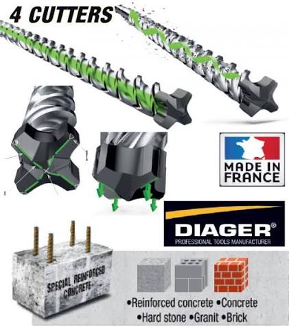
The Head Photos Show Different Visible Profiles
The first close-up emphasises the raised cross-shaped cutting outline and the transition into the spiral. The second exposes more of the head’s side faces and clearance recesses. Edge width, centre shape, visible side height and the head-to-flute entrance can all look different across these views.
Those are useful observations, not merely a reason to place every photograph under one generic “four-cutter” caption. At the same time, perspective, diameter, finishing and illustration style influence the silhouette. These images are not a SKU-matched section drawing that proves two separately marketed material constructions.
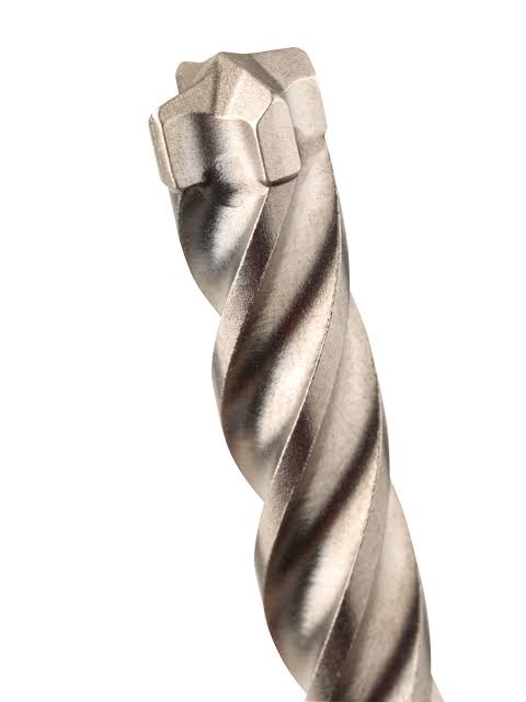
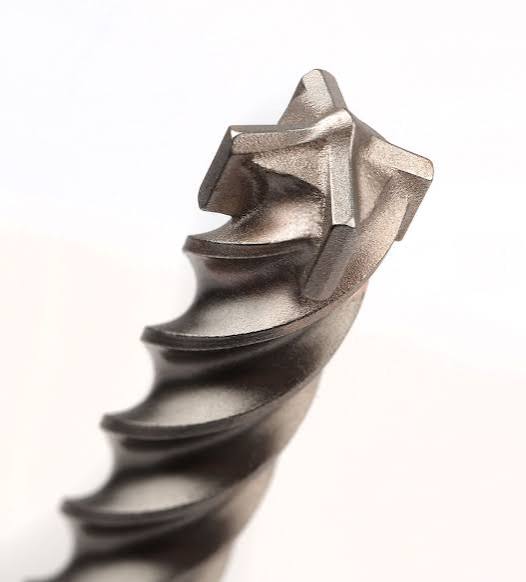
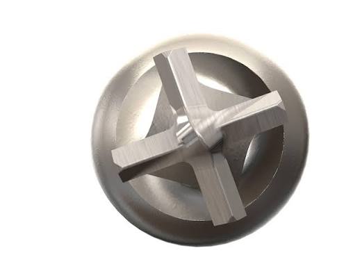
The end view below adds a third perspective: it shows the four cutting positions and the space between them. Read the front face together with the side profile rather than using one cross-shaped outline to classify the whole head.
Monobloc, Full-Carbide Head and Joining Are Separate Fields
The terminology becomes clearer when each description answers a different question:
| Description | What it identifies | Purchasing field |
|---|---|---|
| Four-cutter | Number of cutting edges | Actual cutting-edge count of the selected SKU |
| Monobloc carbide component | One integrated carbide part | Component geometry and extent of steel support |
| Full-carbide head | Carbide construction of the working head | Working crown, base and connection to steel |
An integrated carbide part can be described as both monobloc and full-carbide head, depending on its shape and the manufacturer’s terminology. For a steel-supported cross insert, specify the insert and support seats. For a full-head construction, specify the complete working head and its steel connection. Joining method is confirmed separately.
Diager’s English Ref.112 page uses the broad description “monobloc carbide tip”. Its French Ref.112 specification and 2026 catalogue explicitly describe a massive monobloc 100% carbide head. That supports the published full-head positioning; it does not assign every detached image to a verified production version.
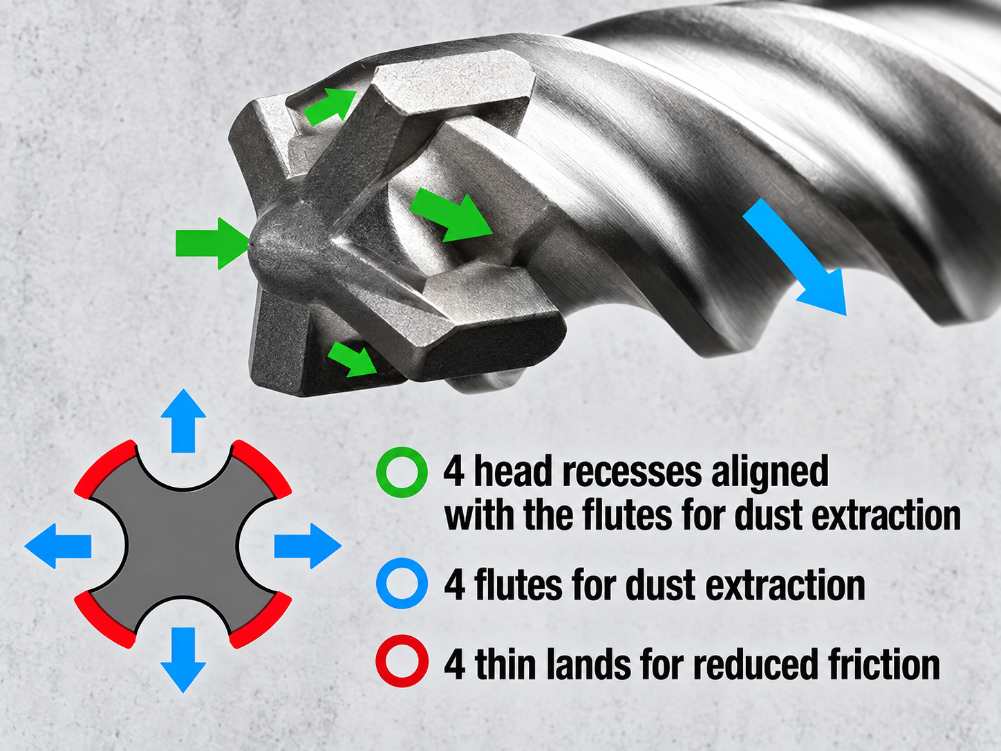
Head Recesses, Four Flutes and Body Lands
Four head-clearance openings and the spiral channels form a debris route from the cutting face towards the hole exit. Compare the throat behind the cutters, groove section, pitch and remaining steel core as one system. The four same-height cutters and outer gauge geometry also matter to the hole diameter as the bit wears.
The arrowed reference below helps locate head recesses and flute paths. Its head-side callouts and Diager’s published broad body lands refer to different locations. Measure head relief and body-land width separately on the drawing; the annotation is a visual aid rather than a material cross-section.
For anchor work, evaluate worn hole diameter alongside edge condition and the anchor manufacturer’s drilling and cleaning requirements. A drilling sample should also record hole time, debris clearance and tracking at reinforcement encounters.
Ref.112 Sizes and the Six-Cutter Catalogue Footnote
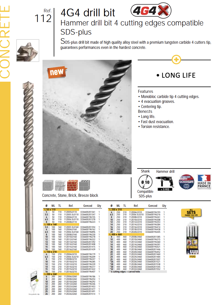
The official Ref.112 tables give diameter, working length and overall length independently. The following selection includes the explicit 2026 page-19 footnote: the starred Ø26, Ø28, Ø30 and Ø32 references at 460 mm overall are listed with six cutting edges and a machined helix. These are specific catalogue entries, so the 4G4 family name alone is not the complete head specification.
| Item code | D (mm) | Working length (mm) | Overall length (mm) | Cutters |
|---|---|---|---|---|
| 112D05L0110 | 5 | 50 | 110 | 4 |
| 112D05.5L0160 | 5.5 | 100 | 160 | 4 |
| 112D06L0260 | 6 | 200 | 260 | 4 |
| 112D06.5L0210 | 6.5 | 150 | 210 | 4 |
| 112D08L0460 | 8 | 400 | 460 | 4 |
| 112D10L0310 | 10 | 250 | 310 | 4 |
| 112D12L0210 | 12 | 150 | 210 | 4 |
| 112D14L0460 | 14 | 400 | 460 | 4 |
| 112D16L0160 | 16 | 100 | 160 | 4 |
| 112D20L0260 | 20 | 200 | 260 | 4 |
| 112D26L0460 | 26 | 400 | 460 | 6* |
| 112D28L0460 | 28 | 400 | 460 | 6* |
| 112D30L0460 | 30 | 400 | 460 | 6* |
| 112D32L0460 | 32 | 400 | 460 | 6* |
* Six cutting edges plus machined helix, as marked for these four 460 mm catalogue references. Example: 112D08L0460 is Ø8 × 400 mm working × 460 mm overall; 112D32L0460 is Ø32 × 400 × 460 mm with the six-edge footnote.
112, 112Q, 157K and 157L Identify Different Order Formats
The order references first identify a single-bit range, a mixed set or a quantity pack:
| Reference | Order format | What to confirm |
|---|---|---|
| 112 / 112D… | Single-bit family and complete size code | Diameter, both lengths, cutter count and head construction |
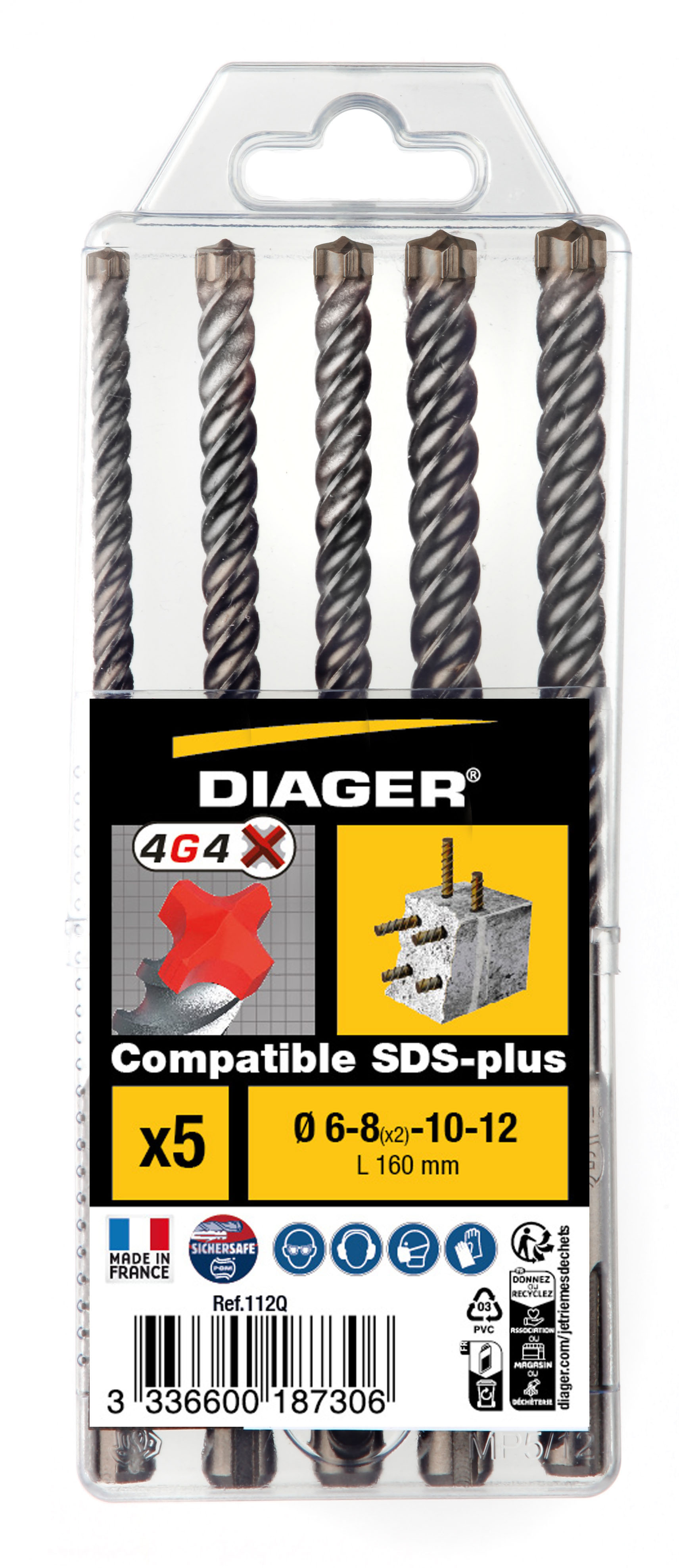
| 112Q | Five-piece mixed set | Ø6, 8, 8, 10 and 12 mm; all 160 mm overall |
| 157K / 157KD… | Six pieces of the selected size | Exact pack size reference and dimensions |
| 157L / 157LD… | Twelve pieces of the selected size | Exact pack size reference and dimensions |
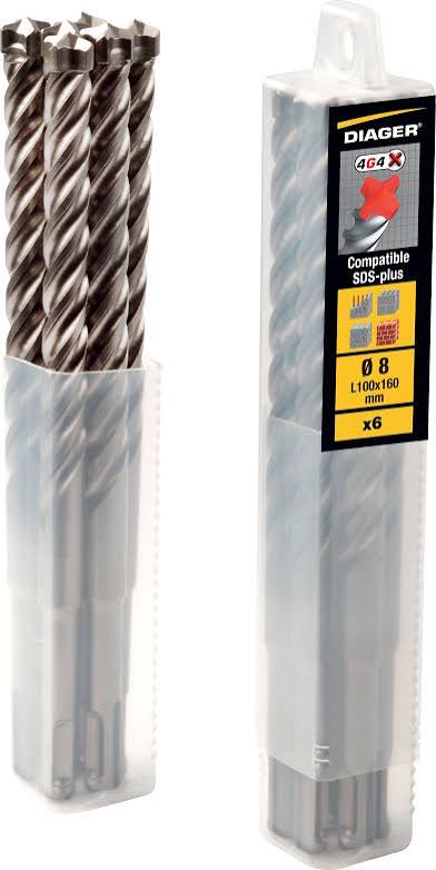
The 112Q set page gives Ø6–8(x2)–10–12 at 160 mm overall. The original package photo makes the quantity and repeated Ø8 size easy to see. The bulk-tube photo illustrates another order format; identify its exact pack from the label and full code.
English and French pages also retain different wording in places. For example, the French 157L heading mentions three cutters while its detailed description lists four. Use the detailed product specification and catalogue footnotes together. Pack quantity is not evidence that one code means a conventional insert and another a full-carbide head.
Our SDS-Plus OEM Selection Route
At Zhonghuan, we develop SDS-Plus drill bits around substrate, reinforcement exposure, hammer and hole dimensions. We specify the carbide component, steel support, joining route, flute transition and final gauge as separate features, then coordinate them in an approved sample.
Proposed configuration A: an integrated four-cutter insert programme with support and joining defined on our drawing. Proposed configuration B: our ZHPLUS-8 full-carbide-head programme within the confirmed supply matrix. Engineering confirms diameter/length combinations and sample acceptance for the target work.
Send the benchmark image or reference, hole diameter and depth, hammer model, concrete/rebar conditions and quantity per size. We can confirm the construction, marking, packaging and quotation. See our monobloc and full-carbide terminology guide and SDS OEM programme.
Discuss a four-cutter SDS-Plus OEM range
Frequently Asked Questions
Do the different photographs prove two separate 4G4 construction lines?
They show different visible head profiles. The supplied views do not map those profiles to two manufacturer-defined material versions by SKU. Compare the selected part, drawing and head-to-steel boundary.
Can monobloc and full-carbide head describe the same part?
Yes. Monobloc identifies a one-piece carbide component, while full-carbide head describes the working-head construction. Define steel support and the joining route separately.
Is every Ref.112 entry a four-cutter?
The 2026 catalogue explicitly marks 112D26L0460, 112D28L0460, 112D30L0460 and 112D32L0460 as six cutting edges plus a machined helix. Use the specific item code and footnote.
Are 112Q, 157K and 157L head-construction codes?
They identify order formats: a five-piece mixed set, a six-piece size pack and a twelve-piece size pack respectively. They do not independently define the head material or joint.
What is in the 112Q set?
Five 4G4 bits in Ø6, 8, 8, 10 and 12 mm, all 160 mm overall length. Confirm current package details against the selected order reference.
Official Sources
- Diager — English Ref.112 product page
- Diager — French Ref.112 head construction and flute description
- Diager 2026 catalogue — pages 18–19, variants; page 54, mixed set
- Diager — 112Q five-piece set
- Diager — 157K six-piece size packs
- Diager — 157L twelve-piece size packs
References checked on 26 October 2026. Product photographs, catalogue extracts and annotated reference illustrations are identified by their roles; the selected SKU defines the supply specification.


