

Where Booster Plus 113 Fits
Diager Booster Plus 113 is a professional three-cutter SDS-Plus reference for concrete and reinforced concrete. Its design combines a self-centring carbide tip, three working edges and a flute shaped to transport drilling debris. Diager’s product specification positions the family around accurate starts, calibrated holes and fast dust evacuation.
Start selection with the concrete, aggregate and reinforcement, then the hammer and hole dimensions. The 2026 catalogue illustrates the SDS-Plus platform with a rotary hammer below 5 kg; select the actual machine by its permitted drilling range. Planned intersections with structural reinforcement follow the project-approved drilling and cutting plan.
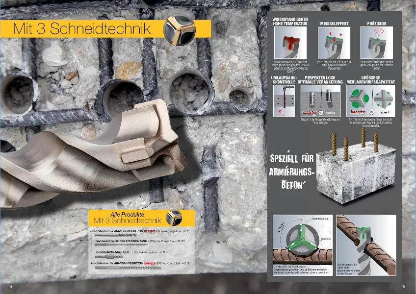
Three Cutting Edges on One Carbide Insert
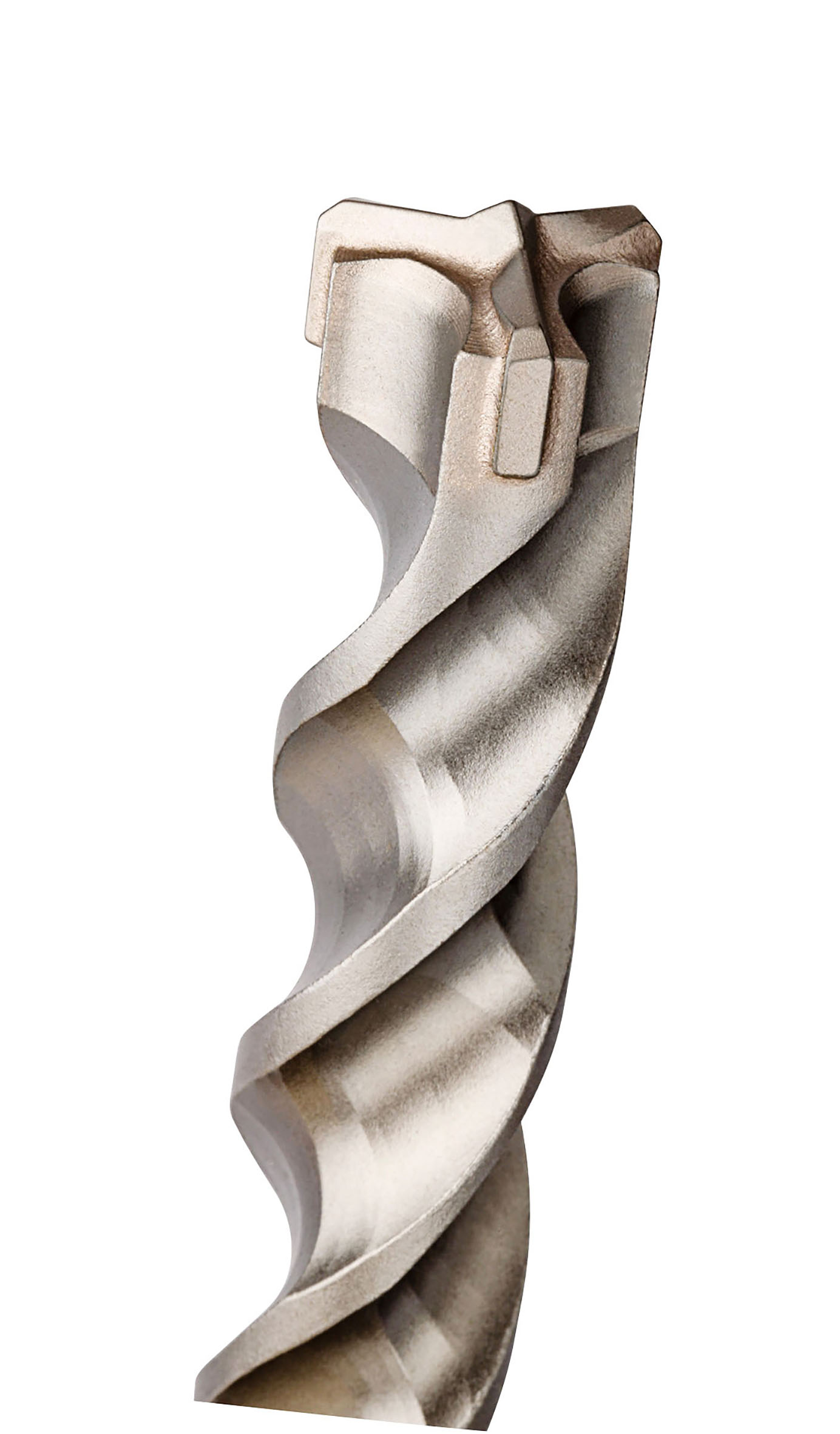
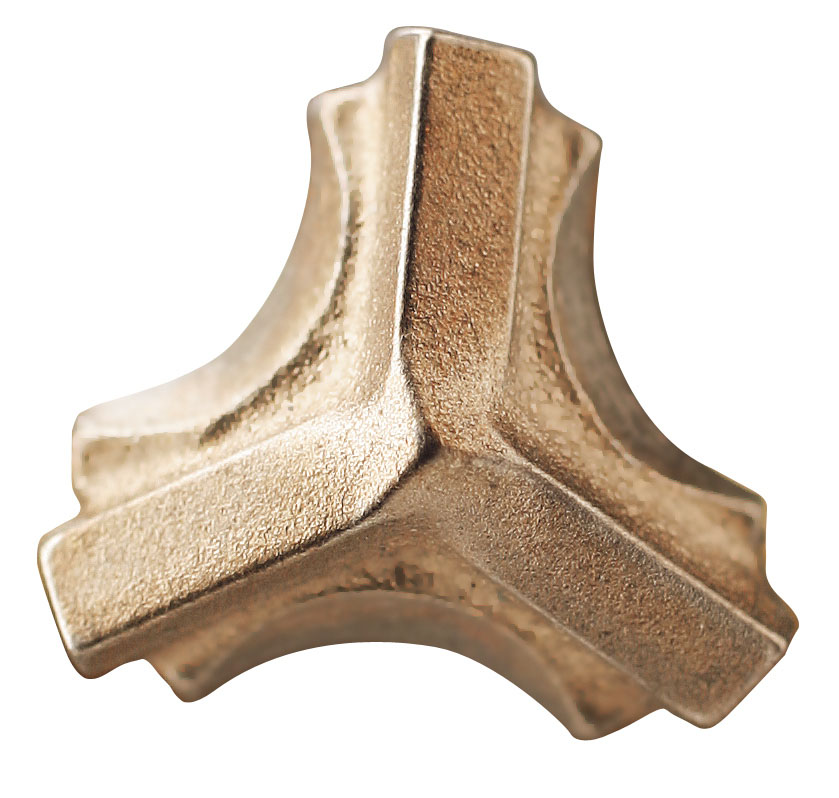
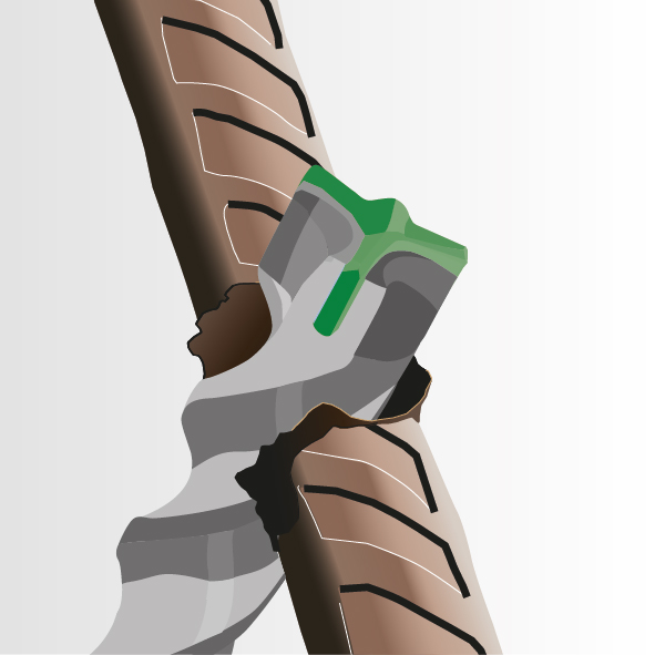
The loose-component photograph is particularly useful: the three cutting arms belong to one shaped carbide insert. The assembled views show how the steel head supports that insert and connects it to the fluted body. Three cutters therefore describe three cutting edges, while monobloc describes the single carbide component.
The centre establishes the first contact with the material. The three-edge arrangement adds working contact around the bore. When comparing samples, look at the point, edge height, outer gauge, carbide support and the open entry into the flute together. These are the features that connect starting accuracy with continued drilling.
120°, 135° and 150° Describe Different Things
The drawings and specifications use several angles. Keeping their definitions separate makes the product easier to identify:
| Angle | Source / view | Meaning |
|---|---|---|
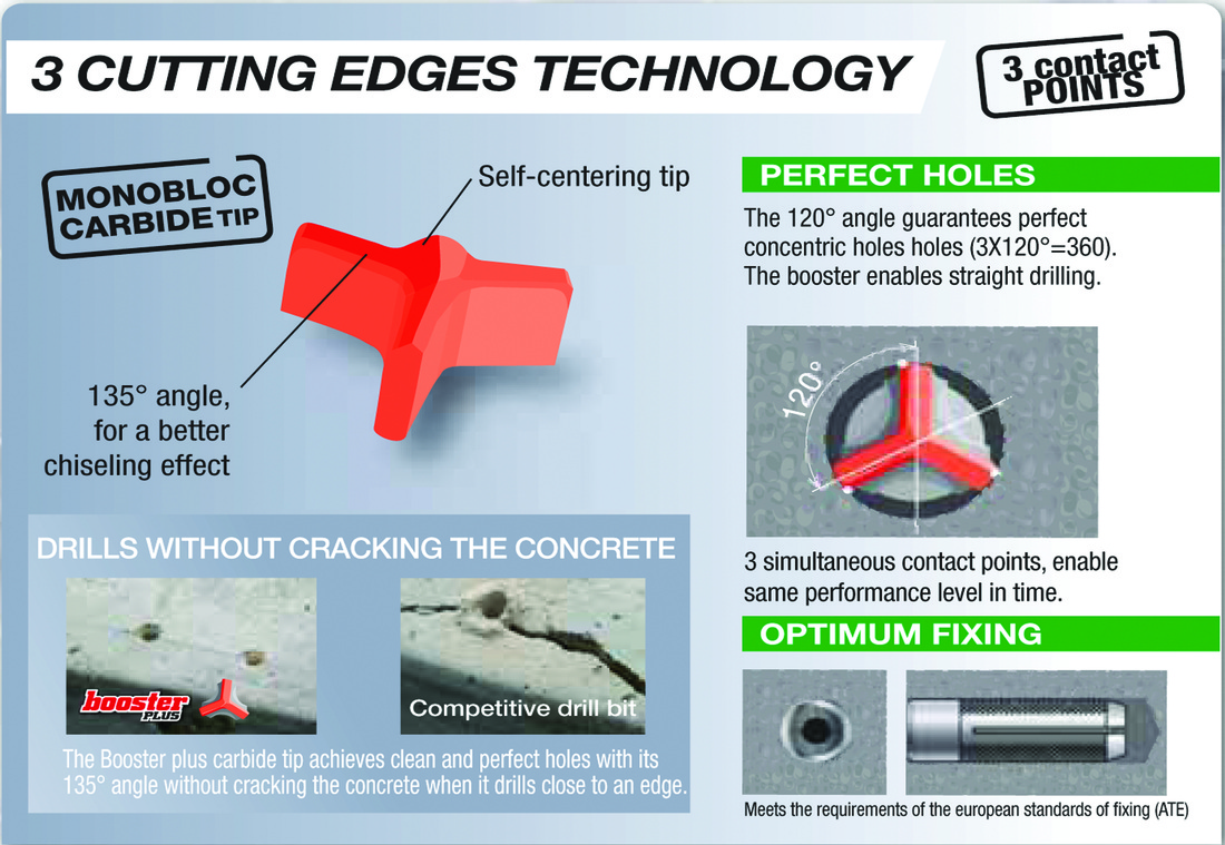
| 120° | Original end-view diagram | Three cutting-edge positions around the drill axis: 3 × 120° = 360° |
| 135° | Earlier Diager literature, including the 2017 catalogue | Published tip-angle description for that reference material |
| 150° | Diager Booster Plus product page | Tip angle listed in that product specification |
Use the selected SKU’s technical drawing for the supplied tip geometry. The 120° spacing is a different measurement from the point angle. The older original diagrams remain useful for reading the three-edge layout and contact positions.
The Flute and the Complete Dust Path
Dust removal starts directly behind the carbide. Crushed material needs an open transition from the head into the spiral, then a continuous path towards the hole exit. Flute section, pitch, steel core and transition radii work together; a distinctive outside shape is only part of that geometry.
Diager’s French product page describes half-round and square flute machining, while the 2026 catalogue highlights the half-round flute. Earlier Booster literature also explains a TRI-ZONE dust path through clearance, acceleration and extraction regions. Section shape and the work assigned along the body are separate ways of describing the system.
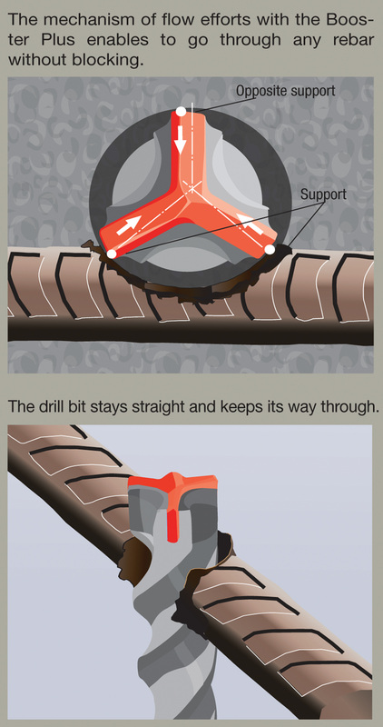
For sample acceptance, compare sustained hole progress, debris clearance, edge condition and finished-hole diameter at the same drilling depth. At rebar contact, also record stalls and the head’s tracking under uneven engagement.
Diameter, Working Length and Overall Length
The 2026 catalogue, pages 20–21, gives diameter, useful working length and total length separately. The following references cover several common combinations; they are a selection from the catalogue, not every possible size.
| Item code | D (mm) | Working length (mm) | Overall length (mm) |
|---|---|---|---|
| 113D05L0110 | 5 | 50 | 110 |
| 113D05.5L0160 | 5.5 | 100 | 160 |
| 113D06L0260 | 6 | 200 | 260 |
| 113D06.5L0210 | 6.5 | 150 | 210 |
| 113D08L0460 | 8 | 400 | 460 |
| 113D10L0610 | 10 | 550 | 610 |
| 113D12L0310 | 12 | 250 | 310 |
| 113D14L0160 | 14 | 100 | 160 |
| 113D16L0210 | 16 | 150 | 210 |
| 113D18L0260 | 18 | 200 | 260 |
| 113D20L0460 | 20 | 400 | 460 |
| 113D20L0610 | 20 | 550 | 610 |
For example, 113D08L0460 is Ø8 mm with 400 mm working length and 460 mm overall length. Confirm all three dimensions from the item code’s row rather than treating the printed overall length as hole depth.
Reading the Original 113D Seven-Piece Set
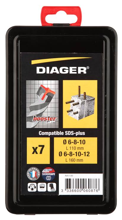
The pictured 113D seven-piece metal set contains Ø6, 8 and 10 mm bits at 110 mm overall length, plus Ø6, 8, 10 and 12 mm at 160 mm overall. Repeated diameters provide different reaches. The official set page and the catalogue’s set table identify this combination.
Keep the complete single-bit code, such as 113D08L0460, distinct from the set reference 113D. For distributor replenishment, record the set composition and the quantity required for each frequently consumed single size.
Choosing a Two-Cutter, Booster or Full-Carbide Head
Choose the head around the job and the required hole quality. Cutter count, carbide architecture and head-to-steel connection should each appear in the specification:
| Construction reference | What to identify | Useful sample comparison |
|---|---|---|
| Twister Plus two-cutter | Self-centring two-edge tip and its dust path | Starts, drilling time and debris removal in the target masonry/concrete |
| Booster Plus three-cutter | Three-edge monobloc insert, steel support and flute transition | Hole tracking, gauge retention and behaviour at reinforcement encounters |
| Full-carbide-head programme | The complete carbide crown and its connection to the steel body | Head geometry, joint, wear and finished-hole dimensions under the same conditions |
Our separate Booster vs full-carbide-head comparison examines the architecture in more detail. The original load diagram below illustrates the three-contact-point concept; use application samples to compare actual behaviour.
Our SDS-Plus OEM Development Route
At Zhonghuan, we manufacture SDS-Plus drill bits and develop the head and dust path as one system. We define the carbide component, steel support, joining route, flute section and working dimensions against the intended substrate and hammer platform.
Proposed configuration A: a three-cutter insert-head programme with the tip, support and size schedule confirmed on the approved drawing. Proposed configuration B: a full-carbide-head programme within our confirmed supply range, with its head-to-steel connection and test criteria agreed during engineering review.
Send the benchmark reference, hole diameter and depth, hammer model, concrete/rebar conditions and quantity per size. We can confirm the sample plan, marking, packaging and quotation. See our SDS OEM programme and head-joining guide.
Discuss a 3-cutter SDS-Plus OEM range
Frequently Asked Questions
Does Booster Plus use three separate carbide pieces?
The illustrated Booster Plus tip is one shaped carbide insert that forms three cutting edges. The surrounding steel support is part of the assembled head.
Why do the materials show 120°, 135° and 150°?
120° is the end-view spacing between three cutting positions. Earlier literature uses a 135° tip angle, while the product page lists 150°. Specify the selected SKU’s actual tip geometry from its drawing.
Is a monobloc carbide insert the same as a full-carbide head?
Monobloc identifies a one-piece carbide component. The illustrated Booster insert is supported within the steel head. A full-carbide-head specification separately defines the complete working crown and its connection to steel.
What is included in the 113D set?
Seven Booster Plus bits: Ø6, 8 and 10 mm at 110 mm overall length; Ø6, 8, 10 and 12 mm at 160 mm overall length.
How should an OEM Booster benchmark be compared?
Use the same substrate, hammer, diameter and depth. Compare starting accuracy, completed-hole time, dust clearance, head tracking and worn hole dimensions, with the head construction and joining route recorded.
Official Sources
- Diager — Booster Plus 113 product specification
- Diager — French product page, tip and flute descriptions
- Diager 2026 catalogue — sizes on pages 20–21 and sets on page 54
- Diager 2017 English catalogue — earlier 135° tip-angle description
- Diager — 113D seven-piece set
References checked on 26 October 2026. Original diagrams retain their source wording; the selected SKU and drawing define the supply specification.


