

Two interfaces, three active edges
Three-cutter SDS bits use three active carbide cutting edges. SDS-Plus and SDS-Max versions can share that edge-count description while requiring different bodies, machine interfaces and head support. Start with concrete, aggregate, reinforcement and hole depth, then match the hammer and bit construction.
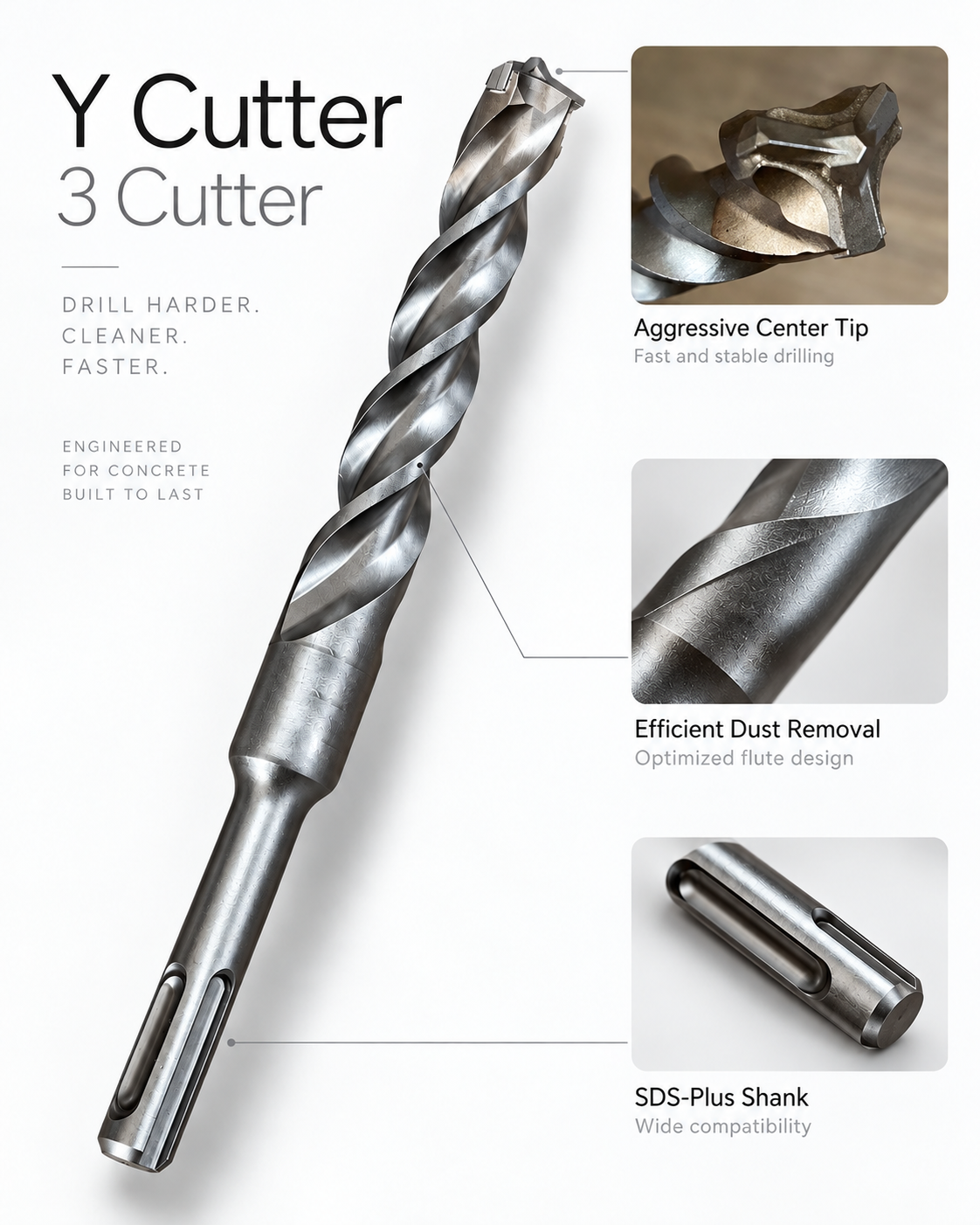
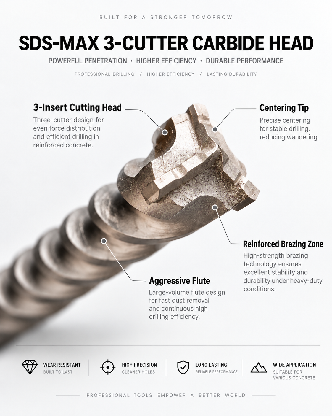
Cutting edges, inserts and flutes
The carbide edges break and cut material; the centering feature guides the start; the steel flutes transport debris. Edge count describes the cutting head. Flute count describes the body. Count the working edges from the end and side views rather than inferring them from the spiral.
Insert count is a separate construction detail. One full-width carbide blade can provide two opposing cutting edges. The supplied illustrations both show three active edges; the second image also identifies its three insert components. A drawing should record those two quantities separately.
SDS-Plus: anchor and installation holes
For routine anchor and installation holes, assess starting accuracy, drilling rate, usable length and the weight of the hammer-and-bit combination. Repeated overhead work makes balance and reliable dust removal especially valuable. Select the diameter and embedment depth required by the fixing system.
Longer holes, hard aggregate and reinforcement contact increase the importance of chip clearance and edge support. Use the anchor manufacturer’s hole specification and the project’s reinforcement requirements when choosing the drilling location and method.
SDS-Max: support and chip clearance
For larger or deeper holes on an SDS-Max hammer, body strength, chip space, support beneath the carbide and joint quality carry more weight. Specify the actual hammer model and impact energy together with diameter, working length and overall length. SDS-Plus and SDS-Max are different interfaces.
A three-cutter label alone does not establish a universal speed or life ranking against four- or six-cutter heads. Compare drilling time, finished diameter, wear and behavior at reinforcement on the same substrate, machine and hole geometry.
Inserted heads and full-carbide heads
An inserted head combines separate carbide components with seats in the steel body. Positioning, support area, edge-height control and joining quality define the assembly. A full carbide head (FCH) forms the cutting head as one carbide component, which is then joined to steel. Both constructions can have three active cutting edges, with different carbide volumes and manufacturing routes.
A professional reference and an OEM specification
Makita B-61117 is a 1/2 in × 12 in SDS-Plus three-cutter positioned for reinforced concrete, with centering and guiding features. Its nominal dimensions are approximately 12.7 × 304.8 mm; compare cutting diameter, working length and total length separately from a 12 × 310 mm metric bit. Makita B-61117
For a Zhonghuan sample comparison, send the hammer model, material, hole diameter and depth, plus the preferred inserted or full-carbide construction. We use these inputs to agree the head configuration, steel-body specification and sample-drilling acceptance before repeat supply.
Full carbide head three-cutter geometry · SDS-Plus · SDS-Max · Request a sample

