

One Head Family, Two Geometric Configurations
Both heads in the supplied comparison belong to the multi-insert X-type, or cross-head, four-cutter family. They are not two different carbide-component counts. The useful distinction is how the primary blade, side inserts, steel seats and flute entrances work together.
Our ZHMAX-7 programme uses a full-width primary carbide blade plus two inclined, axially set-back side inserts for heavy reinforced-concrete and deep-hole work. This article compares that configuration with the compact side-insert reference shown beside it, then turns the visible differences into drawing and test fields.
Four cutting edges can come from three carbide pieces: the primary blade supplies two leading edges, while each side insert contributes one peripheral edge. “Split” here means separate components permanently brazed into the steel head. These are not replaceable indexable milling inserts.
How the Six Reference Images Group Together
| Reference group | Images | Visible configuration |
|---|---|---|
| Compact side-insert cross reference | 1, 5 and 6 | A continuous roof-like primary-blade profile and compact exposed side-insert faces near the head end |
| ZHMAX-7 staged side-insert configuration | 2, 3 and 4 | Full-width primary blade, inclined side inserts and a visible change in their axial position relative to the primary edge |
This grouping follows the assembled geometry, rather than copper/grey colour or an assumed brand. The end-view cross is a stationary arrangement; as the bit rotates, its outer gauge-cutting edges sweep a circular envelope. It is not intended to drill a cross-shaped hole.
Compact Side-Insert Cross Reference
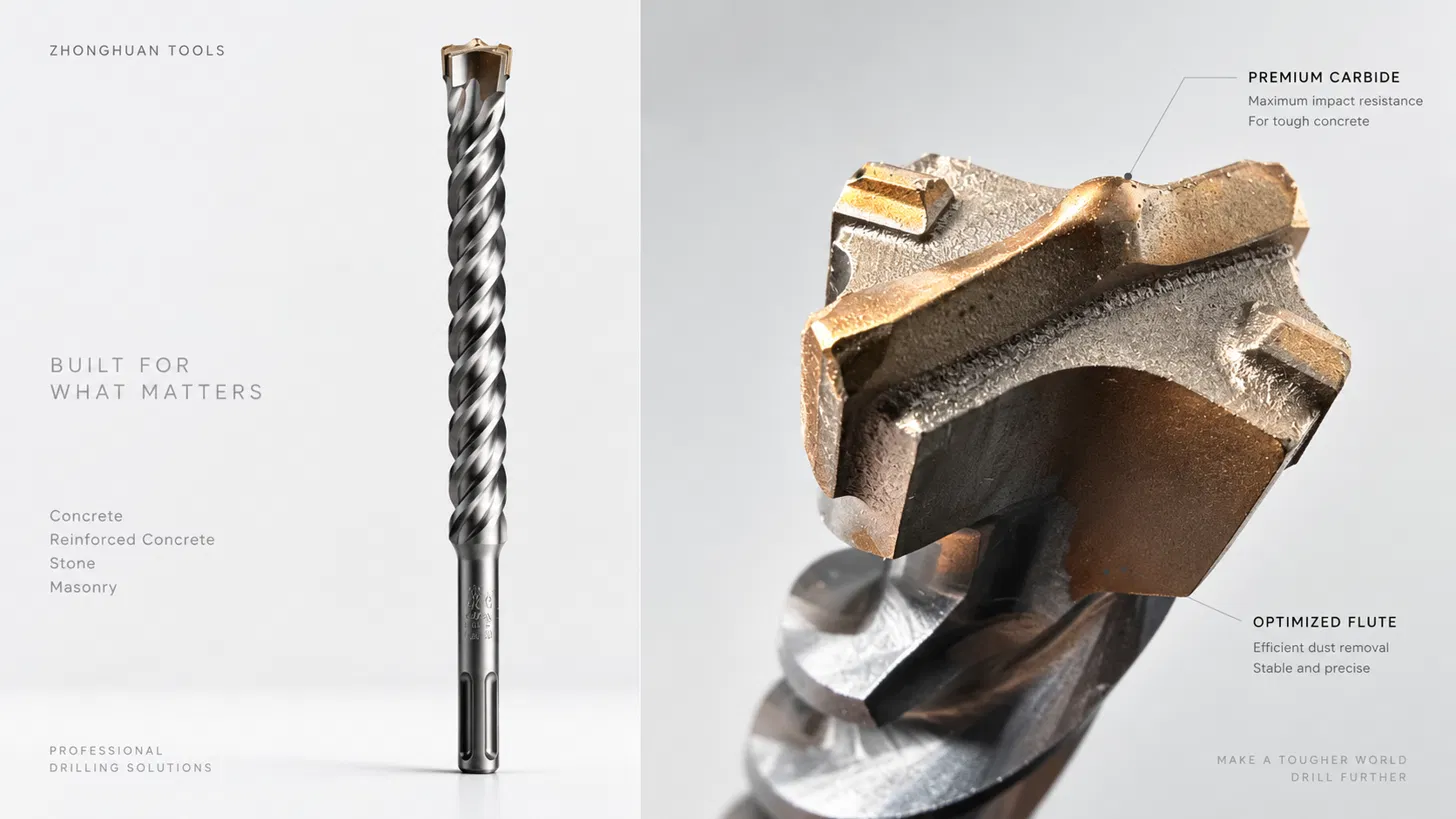
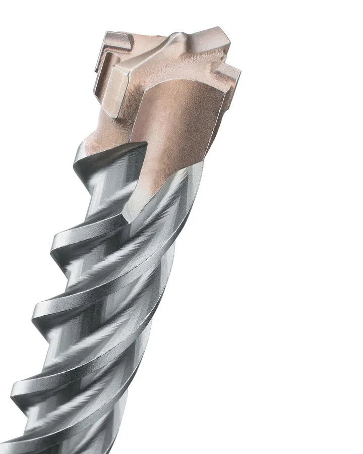
Reference image 1 shows the assembled head and body. The compact description refers to the visible side-insert arrangement, not a measured total insert length.
ZHMAX-7 Primary Blade and Side Inserts
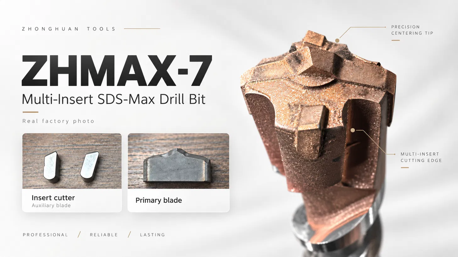
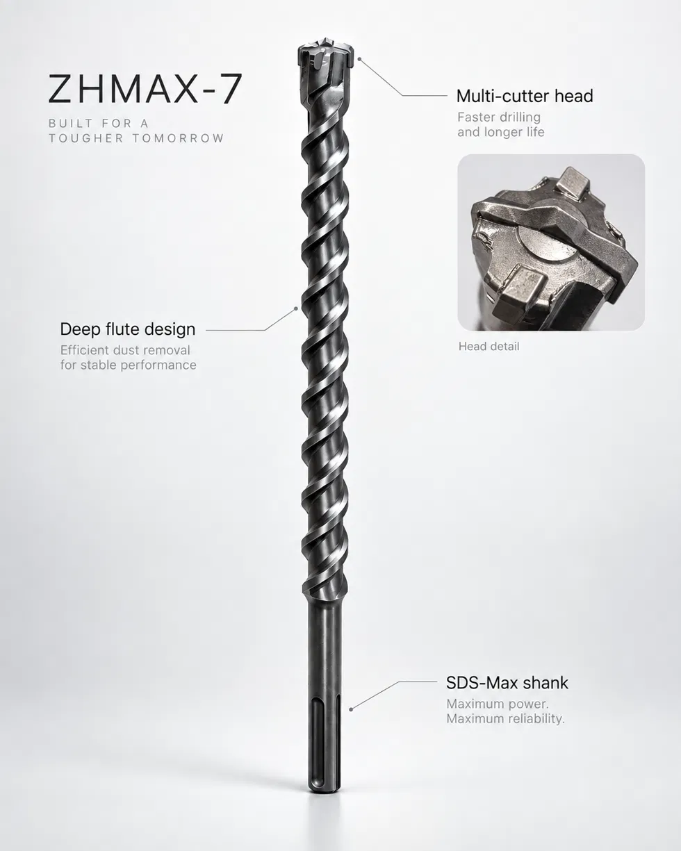
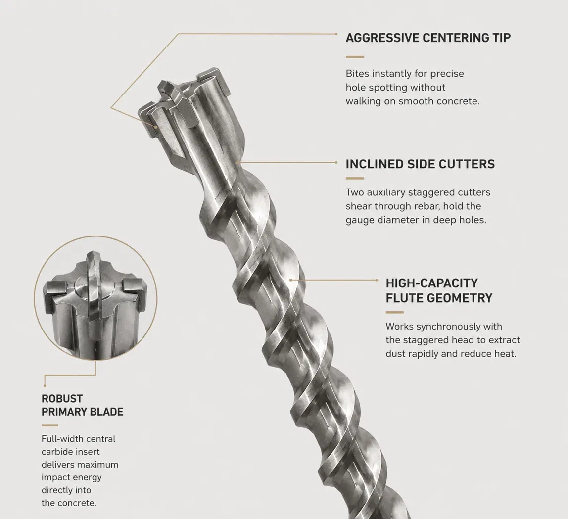
The assembled head and loose components identify the full-width primary blade and the two side inserts. Individual image panels do not establish a common measurement scale.
Where the Cutting Geometry Differs
| Field to compare | Compact reference | ZHMAX-7 configuration | Drawing or measurement |
|---|---|---|---|
| Primary-blade profile | Roof-like cutting profile with a central high point | Full-width primary blade with a distinct centre and stepped / relieved outline in the supplied views | Centre-point height, edge angles and relief behind the cutting edges |
| Side-insert inclination | Compact exposed faces; orientation follows the selected design | Inclined side inserts with defined seating orientation | Angle of each insert and position relative to the rotation direction |
| Axial setback | Side edges also appear below the primary edge; setback is not exclusive to one group | Two side inserts are axially set back from the primary cutting edge | Primary-to-side-edge height difference at the actual diameter |
| Outer gauge geometry | Outer cutting corners establish the rotating diameter | Peripheral cutting edges and support are configured for stable gauge retention | Radial projection, gauge edge length and its wear path |
| Carbide support | Effective support is inside the prepared steel seats | Separate primary and side seats support the staged geometry | Pocket depth, seating contact and supported carbide section |
The centering action comes from the leading carbide point and cutting geometry. A circular bright area around the centre can be part of the support or relief geometry; its shape alone does not prove a separate “round-platform centering” mechanism.
A visibly longer side face may indicate a different exposed profile, but it does not reveal the buried insert length or effective brazed area. Compare loose parts and the actual seat drawing. Both designs still have one primary component and two side components.
Gauge Retention and Dust Flow Belong to the Complete Bit
Head geometry controls where the impact engages; the flute transition controls where the broken concrete and steel fragments can leave. Compare the open head pockets, throat into the flute, groove cross-section, pitch and steel core at the same nominal diameter.
ZHMAX-7 combines staged side engagement with open head pockets and a flute arrangement intended to sustain deep-hole debris clearance and hole tracking. A larger-looking groove in an oblique photograph is not a volume measurement. Groove capacity and core strength need to be considered together.
Gauge retention is the ability to keep the finished-hole diameter within the agreed requirement as the outer edges wear. It depends on carbide, gauge-edge geometry, support, abrasive aggregate and the drilling setup; a side insert’s length alone does not determine it.
Compare the Seats and Joining, Not the Surface Colour
Copper-coloured and grey heads can reflect joining appearance, finishing, lighting or image treatment. Specify the approved finish separately from carbide grade and head geometry. Colour is not a carbide hardness or joint-strength scale.
For our ZHMAX-7, we coordinate primary and side seating geometry with controlled-atmosphere mesh-belt brazing. Effective joint contact, fit, filler distribution and inspection matter more than the apparent length of a visible braze line.
Both reference designs contain three carbide components. Material cost follows the measured carbide volume and grade; manufacturing cost also follows pocket machining, fixtures, assembly orientation, process time and yield. Use the two drawings and BOMs for a cost comparison instead of assuming that one configuration must cost more.
Choose the Configuration Around the Drilling Task
| Drilling task | What to compare | Configuration decision |
|---|---|---|
| General concrete and masonry holes | Controlled starts, completed-hole time, dust clearance and tool cost | Compare the compact reference and the selected ZHMAX-7 SKU at the same diameter and reach |
| Reinforced concrete | Stable steel engagement, stalls, edge damage and gauge retention | ZHMAX-7 is our heavy reinforced-concrete programme; match the model to the actual bar crossing and machine |
| Deep holes and abrasive aggregate | Flute throat, debris removal, straightness and worn hole diameter | Assess the complete head and body, with the same extraction and withdrawal routine |
| High-volume anchor work | In-spec holes per tool and completed-hole cost | Select against the approved hole geometry and actual replacement point |
Our current ZHMAX-7 programme covers Ø16–45 mm and 320–920 mm overall length, with the selected working length confirmed independently. It uses YG11C carbide on a heat-treated 42CrMo body. These fields identify the offered programme; they are not measured performance results for the reference photos.
A Practical Matched-Tool Verification Plan
The following is a proposed verification plan for an engineering purchase or an agreed comparison batch. It is a test method, not a report of completed tests. Start with a diameter and working length available in both constructions.
- Match the tools. Use at least three tools of each configuration at a common diameter and working length. For a geometry-focused comparison, keep carbide grade, body steel, joining route and body/flute design matched where practicable. A complete-product comparison should record every difference.
- Match the machine and controls. Use the same rotary hammer, side handle, rated mode, feed approach and dust extraction. For cordless work, keep the battery condition and charging routine consistent. Alternate the drilling order so one design does not always run first.
- Use purpose-made test blocks. Record concrete batch and measured strength, aggregate and reinforcement grade, diameter, position and crossing angle. Include plain concrete and a repeatable reinforcement crossing; keep intentional steel cuts in approved test specimens.
- Measure each hole and the wear. Record depth and elapsed time, stalls / clutch events, fresh and worn cutting diameter, finished-hole geometry at agreed depths, insert damage and head condition. Photograph the head at fixed intervals.
- Use an agreed stopping point. Stop at the specified wear, diameter or damage limit. Report completed holes and valid holes separately, then compare completed-hole cost and replacement frequency.
| Result field | How to record it | What it resolves |
|---|---|---|
| Drilling rate | Completed depth ÷ elapsed drilling time; keep timing boundaries identical | Penetration at the chosen substrate and depth |
| Steel engagement | Time through the controlled bar zone plus stalls / clutch events | Progress and stability at the specified crossing |
| Gauge retention | Fresh / worn tip dimensions and hole geometry against the approved drawing | Useful life for dimension-sensitive holes |
| Head integrity | Dated images of edges, seats and insert retention at fixed intervals | Damage progression and joining condition |
| Completed-hole cost | Tool consumption plus recorded drilling/changeover labour for valid holes | The commercial choice for the customer’s task |
For the next physical comparison, collect the same views at a common diameter and scale:
- Straight end views of both heads, perpendicular to the tool axis, with a scale.
- Two side views rotated 90° apart, showing primary-edge and side-edge heights.
- Loose primary blades and both side inserts with calliper dimensions; identify left/right parts where the drawing requires them.
- Prepared steel seats before brazing and the agreed joint-inspection views.
- The head-to-flute transition and body section, plus the same views after the comparison holes.
Specify the Head Behind the X-Type Label
Specify nominal diameter, working and overall lengths, primary-blade profile, both side-insert angles, axial setback, radial gauge projection, carbide grade, support seats, joining route, flute/core geometry and finish. These fields make “X-type four-cutter” a repeatable production specification.
For a quotation, start with hole diameter, rotary-hammer model and quantity. A reference photo or drawing helps identify the required configuration. We then confirm the head and body specification, marking, packaging and lead time.
Request a ZHMAX-7 / cross-head OEM quotation
ZHMAX-7 · SDS-Max · ZHMAX-7 OEM
Frequently Asked Questions
Are both groups four-cutter cross heads?
Yes. In this comparison, each has a full-width primary blade and two separate side inserts. Three carbide components create four active cutting edges.
Does the cross outline mean the bit drills a cross-shaped hole?
No. The cross describes the stationary edge arrangement. During rotation the outer gauge-cutting edges sweep the circular cutting envelope.
Are both groups full-carbide heads?
No. The compared heads use separate brazed carbide components in a steel head. A one-piece full-carbide head is a separate construction.
Is axial setback unique to ZHMAX-7?
No. The compact reference also shows side edges below the primary edge. Compare the actual height difference, inclination and radial position rather than treating any setback as a unique feature.
Does a longer-looking side insert guarantee longer life?
No single dimension guarantees service life. Compare supported carbide volume, outer gauge geometry, grade, joining and the complete drilling setup using an agreed wear and hole-size limit.
Why not rank the heads by their copper or grey colour?
Colour can change with joining appearance, finishing, lighting or image processing. Head geometry, material specification and inspection identify the construction.
What does Zhonghuan recommend for heavy reinforced concrete and deep holes?
Our ZHMAX-7 programme combines a full-width primary blade, two inclined axially set-back side inserts and a matched head/flute system. Select the model by hole diameter, working reach, reinforcement and the rotary hammer.

